Commonly used fault diagnosis method for CNC machine tools - News - Global IC Trade Starts Here Free Join
1. Understand what the fault occurred under what circumstances
In order to recover the machine tool faster when a fault occurs, the fault condition should be correctly grasped first, and proper handling is the most important. Therefore, the fault condition should be confirmed according to the following.
(1) "When" occurs
日期 The date and time of the failure?
Ÿ Is it happening at runtime? (How long does it take to run)
å‘生 What happens when the power is turned on?
Ÿ Is it happening when thunder, power outage or interference with the power supply?
多次 Have appeared many times? (frequency of occurrence, several times / hour, several times / day, several times / month)
(2) Failures that occurred after "what kind of operation was performed"
CN How does the CNC operate when a fault occurs?
Ÿ (JOG mode / memory (MEM) mode / MDI mode / remote operation mode (RMT)?)
情况 When the program is running...
1) Where is the program executed when a fault occurs?
2) Program number / sequence number?
3) What is the content of the program?
4) Is it happening in the axis movement?
5) Does it occur during M/S/T code execution?
6) Is the program executing when a fault occurs?
æ˜¯å¦ Is the same operation occurring in the same operation here? (confirm the fault in the present)
Ÿ Is the fault occurring when the data is output/output?
Ÿ When a fault related to the feed axis servo occurs:
1) Is there a failure at low speed feed and high speed feed?
2) Is the fault occurring when a particular axis moves?
主轴 When a spindle-related fault occurs, the spindle is running in the acceleration/deceleration state?
(3) The phenomenon of failure
Ÿ Is the screen display normal?
内容 What is displayed on the alarm screen?
Ÿ If the processing size is not accurate:
1) What is the error size?
2) Is the size of the position display screen correct?
3) Is the offset setting correct?
(4) About other information
æ˜¯å¦ Is there any interference source near the device: When the frequency of failure occurs is low, consider the influence of external interference factors of the power supply voltage. Check whether other machine tools and welding machines are connected to the same power supply. If so, check if the fault occurs. There are devices that are up (or running). (interference power check)
Ÿ On the machine side, is there any measure for interference?
Ÿ For the input voltage should be confirmed:
1) Does the voltage change?
2) Is there a phase-to-phase voltage?
3) Is the standard voltage supplied?
2, according to the alarm information for fault diagnosisNowadays, the self-diagnosis technology of CNC system is more and more advanced, and many faulty CNC systems can detect it and generate alarms and give alarm information. When the CNC machine fails, the alarm information is sometimes displayed on the display, and sometimes there is an alarm indication on the numerical control device, the plc device, and the drive device. At this time, these alarm information should be analyzed according to the Manual. In addition, the PLC program designed by the machine tool is more and more perfect, which can detect the malfunction of the machine tool and generate alarm information. Therefore, when the machine tool is alarmed, it is necessary to pay attention to the research and analysis of the alarm information. Some faults can judge the cause of the fault according to the alarm information, thereby eliminating the fault.
For example, a CNC channel grinder using Siemens 810 system will generate the No. 1 alarm display after booting. "BATTERYALARMPOWERSUPPLY obviously indicates that the CNC system is powered off and the battery is dead. After replacing the new battery (Note: Be sure to charge the system) Replace the battery under), reset the fault and return the machine to normal use.
3. Diagnose faults by using the status information of PL(M)CMany CNC systems have PLC input and output status display functions, such as the PLCSTATUS function under the DIAGNOSIS menu of the SIEMENS810 system, the PMC status display function under the FANUCRAM system DGNOSPARAM software menu, and the PLC-I under the DI-AGN menu of the MELDASL3 system of Japan MITSUBISHI. /F function, CHECKDATA function of Japan OKUMA system, etc. With these functions, you can directly observe the instantaneous state of the input and output of the PLC online. The online detection of these states is very useful for diagnosing many faults of CNC machine tools.
Some faults of the CNC machine tool can be diagnosed according to the fault phenomenon and the electrical schematic diagram of the machine tool, and the PLC-related input and output status can be diagnosed.
Most of the faults that occur in CNC machine tools are checked by the PLC device. The mechanism of PLC detection fault is to run the PLC ladder diagram (ie program) programmed by the machine tool builder for a specific machine tool, and make logic judgment according to various input and output states. If a problem is found, an alarm is generated and an alarm message is generated on the display. Therefore, for some PLCs to generate alarm faults, or some faults without alarms, you can analyze the faults of the PLC by analyzing the ladder diagram of the PLC. You can use the ladder display function of the NC system or the external programmer to track the operation of the ladder diagram online. Diagnose the speed and accuracy of the fault.
For example, a CNC grinding machine has an alarm 6025 "Dresser Arm Lower Time out" indicating that the trimming arm has fallen over time. Check the status of the dresser and find that the dresser has fallen. There is no problem in manually lifting the drop dresser. According to the electrical schematic diagram, the trimmer is detected by the position switch 2LS5, and the switch 2LS5 is connected to the input of the PLC 12.5, as shown in Figure 2-5. Find the PLCSTATUS function under the system DIAGNOSIS menu, check the status of 12.5 online, and find that the status of 12.5 is always "0" regardless of whether the trimmer is dropped or raised, indicating that the PLC has not received the trimmer in-position signal. Check the in-position switch 2LS5 and found no problem. Check that the terminal level of 12.5 is “0â€, indicating that the PLC has no problem with the population. Finally, check the line connection and find that the power connection of the switch 2LS5 on the power terminal 34 is off, and the switch is switched again. After the connection is connected to the power supply, the machine fault disappears.
4, using the PL (M) C program (ladder) tracking method to diagnose the faultMost of the faults that occur in CNC machine tools are checked by the PLC program. Some faults can directly display the cause of the alarm on the screen. Some have alarm information on the screen, but they do not directly reflect the cause of the alarm. Some faults do not generate alarm information, but some actions are not performed. In the latter two cases, tracking the operation of the PLC ladder is a very effective way to diagnose the fault. The FANUC0 system and the MITSUBISHI system itself have a ladder display function that directly monitors the operation of the ladder diagram. Because there is no ladder display function for Siemens CNC system, for simple faults, the status of the PLC can be displayed according to the ladder diagram, the status of the relevant input, output and flag bits can be monitored, and the operation of the program can be tracked. The complex fault must be programmed. To track the operation of the ladder diagram.
For example, a CNC grinding machine with Siemens 810 system, the machine does not return to the reference point after starting, and there is no fault display. Check the control panel and find that the indicator light falling off the indexing device is not lit. For safety reasons, the feed axis of the machine tool cannot move as long as the indexing device does not fall. But checking the indexing device has fallen without problems. According to the electrical schematic of the machine tool, as shown in the figure, the output of the PLC Q7.3 control panel on the control panel drops the indicator light. Check the PLC ladder diagram for this purpose.
The ladder diagram for Q7.3 is in the 21 blocks of PB12, as shown in Figure 2-7. Using the programmer to observe the operation of the ladder diagram online, it is found that the flag bit F143.4 is not closed, so that the output Q7.3 has no power. Marker position F143.4 indicates the workpiece indexing table
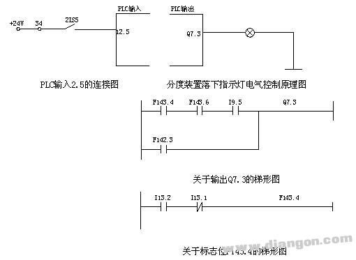
In the drop position, the control ladder is in the 8 blocks of PB10, as shown in Figure 2-8. Use the programmer to view this part of the ladder diagram and find that the F143.4 has no power because the contacts of the input 113.2 are not closed. According to the electrical schematic shown in Figure 2-9, the PLC input 113.2 is connected to the proximity switch 13PS2 that detects the falling of the workpiece indexing device. When the indexing device is disassembled, it is found that there is a problem with the mechanical device, and the mechanical device that drives the proximity switch cannot be driven, so 113.2 cannot always be closed. After the mechanical device is repaired, the machine tool is restored to normal use.
5, using machine data to repair machine toolsSome faults in CNC machine tools are due to unreasonable setting of machine data or adjustments after the machine has been used for a period of time. In the event of such a fault, the corresponding machine data can be modified to correct the fault.
For example, a CNC grinding machine using the Siemens siemens system found that during the grinding process, sometimes the size of the input tool compensation data reflected on the workpiece did not change or the change was too small. According to the working principle of the machine tool, the Z-axis drives the grinding wheel to radially grind the workpiece during the grinding process. When the X-axis is normal, it does not move. Only when the ball center is to be adjusted, the micro-motion is performed.
When measuring the round-trip accuracy of the machine, it is found that the X-axis is allowed to go when it is converted from forward to reverse.
Many CNC systems have a single-step program function, which is used when debugging a machining program. When a machining program failure occurs, the single-step execution program can quickly confirm the fault point and eliminate the fault.
For example, a CNC grinding machine using Siemens 840D system, during the debugging of the machine tool, the foreign technicians clear the data of the numerical control device, re-input the machine data and program, and then debug; when machining the workpiece, the machining program is executed. The system crashes and cannot perform any operations. After the shutdown is restarted, it can still work, but the execution program crashes. I suspect that there is a problem with the machining program, but I have not checked the problem, and this program has been run before. When the program is executed with the single-step function, it is found that each time the crash is executed to N220 of the subroutine L110, the content of the program N220 statement is G18D1, the tool compensation is called, and the tool compensation data is found to be 0, and there is no data. According to the requirements of the machine tool, after the tool compensation value P1 is assigned 10, the machine tool processing program is executed normally, and no crash occurs.
7, intuitive observationThe intuitive observation method is to use the human hand, eyes, ears, nose and other sensory organs to find the cause of the malfunction. This method is very practical in maintenance.
For example, if a quenching machine is turned on, the Y-axis does not go, observe the fault phenomenon, and find that when the Y-axis is moved, the Y-axis does not go, but the coordinate value of the Y-axis on the screen changes normally, and observes Y. The shaft servo motor also rotates normally, so it is suspected that the coupling between the servo motor and the lead screw is damaged, the disassembly check is indeed damaged, and the replacement of the new coupling is eliminated. Another example is that a CNC channel grinder sometimes has an alarm No. 11 indicating that the UMS identifier is incorrect. It may be that the program stored by the machine tool manufacturer in the UMS is not available, or there is a problem during the calling process. The cause of the failure may be a problem with the memory template or the UMS subtemplate. The memory template was removed and inspected. It was found that the connection lines between A and B on the circuit board were corroded and the contact was poor. After soldering the two points, the test was started and no alarm occurred.
8, measurement methodThe measurement method is the basic method for diagnosing machine tool failures. Of course, it is also a common method for diagnosing the failure of CNC machine tools. The measurement method is to measure the electronic circuit using a multimeter, an oscilloscope, a logic tester, and the like.
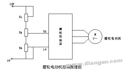
For example, a cylindrical grinding machine with Siemens system, when starting the grinding wheel, the 7021 (GRINDING WHEEL SPEED) alarm appears, indicating that the grinding wheel speed is not normal, the observation wheel is found to be really slow. Analyze the working principle of the machine tool. The grinding wheel spindle is controlled by the Siemens servo module 6SN1123-1AA00, and the speed reference is adjusted by a sliding varistor. The sliding contact of the varistor changes with the position of the diamond roller dresser, so that after the diameter of the grinding wheel is reduced by the simulation method, the given voltage of the rotating speed is increased, the rotating speed of the grinding wheel is increased, and the linear speed of the grinding wheel is kept unchanged. The line connection is shown in Figure 2-10. Measure the voltage between the analog input and the terminals of No. 56 and No. 14 of the servo module. It is found that it is only about 2.6V. Because the given voltage is low, the grinding wheel speed is low. According to the principle analysis, R3 is inside the grinding machine, and its sliding contact follows the diameter of the grinding wheel. Because the working environment inside the machine is bad, it is easy to damage, and there is no problem in measuring R1 and R2, the power supply voltage is also normal. For this reason, Ra was removed and checked, and it was found that there were many grinding fluids in the cable plug. After cleaning, the resistance value was measured to be normal, reinstalled, and the machine fault was eliminated.
Another example is that a CNC grinding machine can not find the reference point on the Z axis. When the machine returns to the reference point, there is no problem when the X and Y axes return to the reference point. When the Z axis returns to the reference point, the pressure limit alarm occurs. Back. Observe the process of returning the Z-axis to the reference point. After the zero-point switch is pressed, the Z-axis decelerates, but stops until it moves to the limit. According to the principle analysis, it is possible that there is a problem with the zero pulse of the encoder. It is true that the zero pulse of the encoder is checked by the oscilloscope. After the new encoder is replaced, the machine works normally.
9. Interchange method to determine the point of failureSome of the faults of the system, due to the many factors involved, are more complicated, and the interchange method can be used to quickly and accurately locate the fault point.
For example, if a CNC lathe fails, when the spindle rotates, the alarm No. 7006 appears, indicating that the spindle speed is out of tolerance, and the spindle is actually rotated. However, the actual spindle speed is not displayed on the screen, so the spindle encoder is suspected to have problems. The spindle encoder is swapped with the spindle encoder of the other machine, and the other machine has an alarm No. 7006, which determines that the spindle encoder is damaged.
Another example is that a CNC lathe suddenly loses power during normal processing. Press the system start button: the system will not start, and the indicator light on the panel will not light up. Measure the 5V DC power supply of the system power supply. When the start button is pressed, the voltage rises and then quickly drops to zero. Therefore, first suspect that there is a problem with the system power module, but replace the standby power module, the fault remains, indicating that the power module has no problem. Continue to check that the spindle encoder connection cable is broken, a wire is shorted to the ground, and the machine tool returns to normal use after processing.
10. Principle analysisThe principle analysis method is the most basic method for troubleshooting. When other inspection methods are difficult to work, it can be checked step by step from the working principle of the machine tool to finally find out the cause of the failure.
The above describes 10 ways to diagnose CNC machine faults. In the diagnosis of machine faults, these methods are often used in combination, and it is difficult to use a single method. This requires maintenance personnel to have certain maintenance experience, rational and comprehensive use of diagnostic methods, so that machine faults can be eliminated as soon as possible.
In summary, the CNC machine tool is the crystallization of the integration of modern high-tech machines, electricity, light and gas. The electrical system is complex and the pipelines are crossed. How can I quickly identify faults and hidden dangers and eliminate them in time? How can I repair these expensive equipment? This may be a problem in front of maintenance personnel. So how to solve this problem? I feel that we must do the following "five essentials". We must read more information, ask more questions, ask more people, make more data records, summarize more, think more, and observe more practice.
1. To see more information
To see more information on the CNC system. Each machine tool will be equipped with relevant information about the CNC system used, such as operating instructions, parameter specifications, maintenance instructions and so on. The purpose of reading CNC data is to understand the characteristics and functions of various CNC systems and PLC programmable controllers; to understand the alarm and troubleshooting methods of CNC systems; to understand the meaning of NC and PLC machine parameter settings; PLC programming language; to understand the method of NC machining program programming; to understand the operation of the control panel and the contents of each menu; to understand the performance of the spindle and the motor and the characteristics of the drive and so on. Often a lot of CNC data, how to see? Mainly to highlight the key points, to find out the ins and outs, as a maintenance staff, the focus is to thoroughly understand the basic composition and structure of the CNC system, master the direction of the block diagram, power line and signal line, flexible use of the maintenance functions provided by the CNC system, understand each LED The meaning of the indicator light. Then, find out how to set the parameters and the meaning of each parameter and its adjustment method. Finally, learn about the programming of CNC machining programs and the meaning and usage of various instructions. However, each part of the content should have a clear understanding and mastery.
Look at the electrical diagram. Every electrical component on the machine, such as contactors, relays, time relays, etc., as well as the input and output of the PLC, should be indicated on the electrical drawings. As a simple example, for example, KM 1 is a contactor that is activated by the hydraulic pump motor M1, and the direction of its normally open and normally closed contacts is generally indicated on the drawing. Therefore, the normally open or normally closed contact KM1 on one of its corresponding pages can be noted as the hydraulic pump motor on. For a large CNC machine, the electrical diagram has dozens of pages, or even hundreds of pages, to understand that the function of each component takes a long time. Sometimes, one or two times
I still don't know the function of the component. I have to look at it and write it after digestion. Therefore, the starting hydraulic pump motor M1 just mentioned should also clearly indicate which external output of the PLC drives the contactor KM1 to operate, and it is necessary to clear the veins. For some block diagrams in the electrical circuit diagram, such as the driver for each axis, there is only one block diagram. As long as you understand a certain control condition (on-off condition), you can study and consider more detailed things. The electrical symbols of different countries are different, so we must first understand clearly. For the thick PLC list written by the manufacturer, we must also look at it, master its programming language, and perform Chinese translation on the basis of understanding. This can greatly save the time for troubleshooting in the future. If you go to familiarize yourself with the electrical diagrams and PLC statement tables after the fault occurs, it will take a lot of time and often lead to wrong judgments.
Look at hydraulic and pneumatic drawings. In CNC machine tools, hydraulic, pneumatic and electrical are interdependent and inseparable. When performing fault analysis, put the hydraulic, pneumatic and electrical patterns together and read each other, which can achieve twice the result with half the effort. Which solenoid valve does the spindle lock tool act on? What are the corresponding PLC outputs and inputs? In the picture, it is marked in a language that is easy to understand, so that the electrical and mechanical actions are all in the end, and the part that is relatively close to the electromechanical relationship should be focused on. Both understand electricity and understand the machine, mechanical and electrical integration, master a variety of skills, so the ability to solve problems is big.
It is necessary to look at foreign language materials and improve the reading ability of their professional foreign languages. The latest and most advanced numerical control technology in the world today is in the hands of foreigners, which means that their materials must be written in foreign languages. When translated into Chinese, the content began to fall behind. If you don't know foreign languages, especially English, you can't read a lot of the latest and most advanced foreign language technical materials. It is often not ideal to rely solely on translation. Looking at the technical materials of the foreign language version, it is more difficult at the beginning, and there are more words. After reading more, the number of commonly used professional words is so much. It seems to be smooth in the future. A competent maintenance personnel should basically master the language tools.
2. Ask more questions and ask others
If an expert comes to your factory to install and debug the machine, you have the opportunity to participate in that is the best thing. This is the second best learning opportunity, because you can get a lot of first-hand information and methods and techniques for machine tool debugging. For example, how to make corrections after the laser measures the accuracy of each axis. To ask more, if you don't understand, you need to figure it out. Through this period of time, there will be great gains, and you will be able to obtain a lot of materials and manuals for the assembly and debugging of machine tool manufacturers (confidential to users). When the machine tool is put into production, it should always be in close contact with the machine tool builders and experts. Through FAX and E-MAIL, it is very beneficial to ask for solutions and related information to solve the problem of machine tool failure, and to obtain special and special spare parts. At the same time, the agents of the CNC system, such as SIEMENS, FANUC and other companies should also maintain a good relationship. If you ask more questions, you can get the deeper information and spare parts of the CNC system in time, and you will have the opportunity to participate in the special study class on the CNC system.
After the fault occurs, the CNC machine operator should be inquired about the whole process of the fault in detail. Don't ask, or just ask about it. This often leads to incorrect site information, which leads to wrong judgment and complicates the problem. The repair time of the machine tool. Therefore, ask more questions, ask in detail, understand the whole process of the fault (start, middle, end), what alarm signal has been generated, what was operated at that time, what was touched, what was changed, what is the external environment? On the basis of fully investigating the site and mastering the first-hand materials, the failure problems are correctly listed, and half of the problems have been solved, and then analyzed and solved. For experienced operators, they are familiar with machine operation, familiar with machining procedures, and have a good understanding of common machine diseases. Working closely with them is very beneficial for quick troubleshooting.
When other maintenance personnel are repairing the machine tool and you are not going, when they come back, they should also ask more questions. What happened just now? How is he ruled out? Ask him to explain its troubleshooting methods. This is also a good learning opportunity. Learn the skills and methods of correct troubleshooting by others, especially to experienced experienced maintenance personnel, learn their skills and improve their own level.
3. To make more data records for more summary
In the process of daily maintenance and maintenance of CNC machine tools, it is necessary to record various parameters, focusing on various parameters related to machine tool adjustment, such as NC machine parameters, PLC machine parameters, PLC programs, and currents of spindles and servo motors. , voltage, speed and other data. Also note the status (closed or open) of the relays, contactors, etc. in the cabinet during power-on and formal processing, as well as the status of all input and output LEDs of the PLC (light, dark, flashing), or record on the screen. PLC status X (input bit), Y (output bit) is 0 or 1. This record has great benefits for future analysis and judgment of failure.
Carrying a notebook with you, recording the daily faults, especially the faults that have occurred, how to eliminate them one by one, the human brain is long and easy to forget, "good memory, not as bad as a pen." Some faults of CNC machine tools are often repeated, and these faults are often caused. Just check how it is solved at that time. It can be eliminated in a few minutes, which is fast and good. If the company has a equipment repair record, after troubleshooting, remember the troubleshooting method, and bind it to a book for archiving. In this way, a complete historical archive of a CNC machine tool will be available.
4. Think more and think more
Think more, and broaden your horizons. When repairing CNC machine tools, it is often not cool enough, and there is no good comprehensive analysis of the faults. There was a fault. The Y-axis of the WERNER machining center suddenly stopped during machining. The Y-axis grating ruler was repeatedly alarmed on the screen. At that time, the grating scale and the grating head were cleaned twice, and the result was still stopped. It took a few days to solve it, and finally found the real reason. The reason is that there is a problem with the wires between the Y-axis grating head and the amplifier.
Due to the long-term bending of the snake skin tube when the Y-axis moves, one of the position feedback lines breaks to a certain position and causes the machine to stop. At that time, only pay attention to static, ignore the dynamics, there have been control loop open alarms, but did not attract enough attention. Therefore, all the alarms and faults that have occurred should be listed, and the overall judgment and screening should be carried out through the table and the inside, and the maximum probability of failure will be predicted, and then eliminated. "The mountains and waters are full of doubts, there is no way, and the flowers are bright and clear, and another village", thinking, pointing out the direction for you.
5. To observe more practice
For maintenance personnel, be bold and dare to do it. I can only talk about it, don't do it, and can't repair CNC machine tools. But be familiar with the situation and then do it again, don't blindly, otherwise it will expand the fault and cause an accident, and the consequences will be disastrous. At the same time, we must be good at hands-on. First of all, we must familiarize ourselves with the operation panel of the machine tool and the contents of each menu to make it easy to operate. At the same time, we must make full use of the self-diagnosis technology of CNC machine tools to quickly solve the problem. Nowadays, the more developed CNC technology, the more self-diagnosis ability.
Although CNC machine tools are complicated and varied, as long as they are taken seriously, they will be able to rely on their own strength to use, repair and manage CNC machine tools.
Stainless Steel Pressure Gauge
Pressure Gauge Types,Different Pressure Gauge,Trerice Pressure Gauge,Fire Extinguisher Pressure Gauge
Changshu Herun Import & Export Co.,Ltd , https://www.herunchina.com