The basis of the self-control instrument signal circuit and summarize the method of cable section selection
Abstract: Based on the introduction of the self-control instrument signal circuit, the load capacity of the circuit is analyzed. According to the load limitations of several typical two-wire instruments, the longest laying length of the cable is calculated according to the requirements of the design specifications. The longest laying length of different cross-section cables as a function of the meter's power consumption; the two formulas obtained from the intrinsically safe system loop energy constraints also calculate the longest laying length of the intrinsically safe cable. Finally, an example is given to illustrate the selection steps of the cross section of the instrument signal cable.
In the petrochemical engineering design, the cross-section selection of the instrument signal cable is too large, which will cause great waste; if the wire resistance is small, the signal is unstable or the instrument is faulty. Therefore, the author starts from the requirements of the theory and design specifications, calculates the maximum laying length of the instrument signal cable, and summarizes the method of cable section selection.
1 instrument signal circuit
Instrument signals can be divided into 2 categories and 5 types according to the convention, namely analog and digital 2 or AI, AO, DI, DO, PI5 (A - analog, D - digital, P - pulse, I - - input, O - output), where the pulse amount is a special digital quantity with a high frequency of change, so the signal looks like 3 types, but it can be simplified to analog and digital 2, and the output frequency of DO can basically reach the actual Application requirements. Therefore, the control system rarely has a special PO card, and a schematic circuit diagram of the above five signals is shown in FIG.
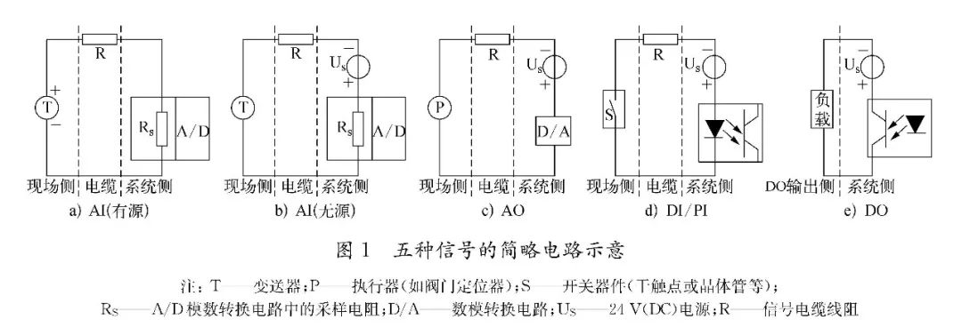
1) The AI ​​signal is the 4~20mA detection current output by the field instrument transmitter. If the field instrument is a three-wire or four-wire connection, the signal output from the transmitter is generally active (except passive external power supply) The detection circuit is shown in Figure 1a); if the field instrument is a two-wire connection, the signal output from the transmitter is passive, and the power supply must be connected to the circuit on the system side. The detection circuit is shown in Figure 1b).
2) The AO signal is the 4-20 mA control current output from the system to the actuator such as the valve positioner. As shown in Figure 1c), except for the components formed in Figure 1b), the two circuits are characterized by signal sum. The power supply shares one loop, often referred to as loop power. Since the loop current is up to 20mA (fault current can exceed 20mA), when the loop resistance is too large, the power supply will not have enough power to maintain 20mA, and the signal will be distorted. Therefore, the loop load must be limited to a certain range, and its load capacity can generally be measured experimentally: First set the meter (field transmitter or AO card), so that the meter is at the maximum loop current setting of 20mA, then Connect the output to the adjustable resistor and connect the ammeter in series to increase the resistance value. When the current gradually decreases with the increase of the resistance value is less than 20mA, the load resistance is the load capacity. Under the 24V (DC) power supply, the field changes. The load capacity of the transmitter is generally 500-600Ω, and the load capacity of the AO card is mostly around 750Ω. Therefore, the signal cable of the same cross-section has a transmission distance of AO farther than AI (the system sampling resistance is 250Ω, and the input impedance of the valve positioner is 250 to 300 Ω).
3) The DI/PI signal refers to the digital quantity (switch quantity) of the access control system. As shown in Figure 1d), the essence of the circuit is to connect the field switch into the loop, and each of the DI/PI cards of the control system The channel load capacity determines the maximum current of the loop. Generally, the maximum current of each channel of the DI card is 5mA, and the maximum current of each channel of the PI card is 40mA.
4) DO signal is equivalent to the control system to supply power to the load, but the DO channel load capacity of the control system card is generally small, about 1W, so the load in the figure is often a relay, and the contact is connected to the electrical through the relay. The secondary circuit controls the motor or serializes the power through the relay contacts and outputs it to an actuator such as an on-site solenoid valve. Therefore, the transmission cable of the DO signal is actually the power supply cable, and the current of the power supply circuit is determined by the power consumption of the electromagnetic valve. The general self-control low-power electromagnetic valve has a power consumption of about 2W and 24V (DC).
2 Cable maximum laying length calculation
The maximum laying length of the cable is directly related to the load capacity mentioned above (the stronger the load capacity, the longer the cable can be laid). The so-called load capacity refers to the maximum loop resistance of the circuit that can work stably. In each circuit, the impedance of each device is fixed at the factory, so the actual loop resistance is mainly determined by the cable resistance R, which determines the signal cable. Section selection and maximum lay length.
2.1 Theoretical calculation
Taking the typical two-wire AI signal as an example, calculate the maximum theoretical laying length of the cable. Generally, the load limitation of the on-site two-wire instrument is shown in Figure 2.
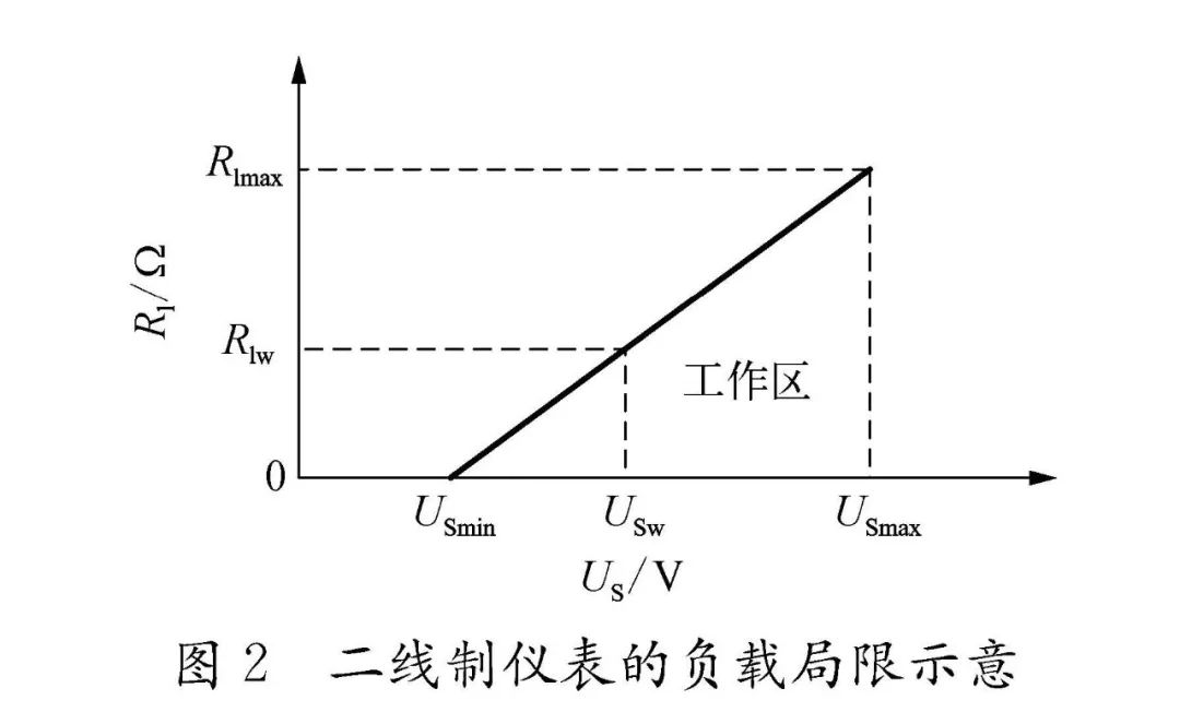
In Figure 2, USmax and USmin respectively indicate the maximum and minimum power supply voltage for the normal operation of the meter. Rlmax is the load capacity at the maximum working voltage. The working area refers to the area where the meter can operate stably. When the power supply voltage is US, the loop load Rl should be Meet the following formula:
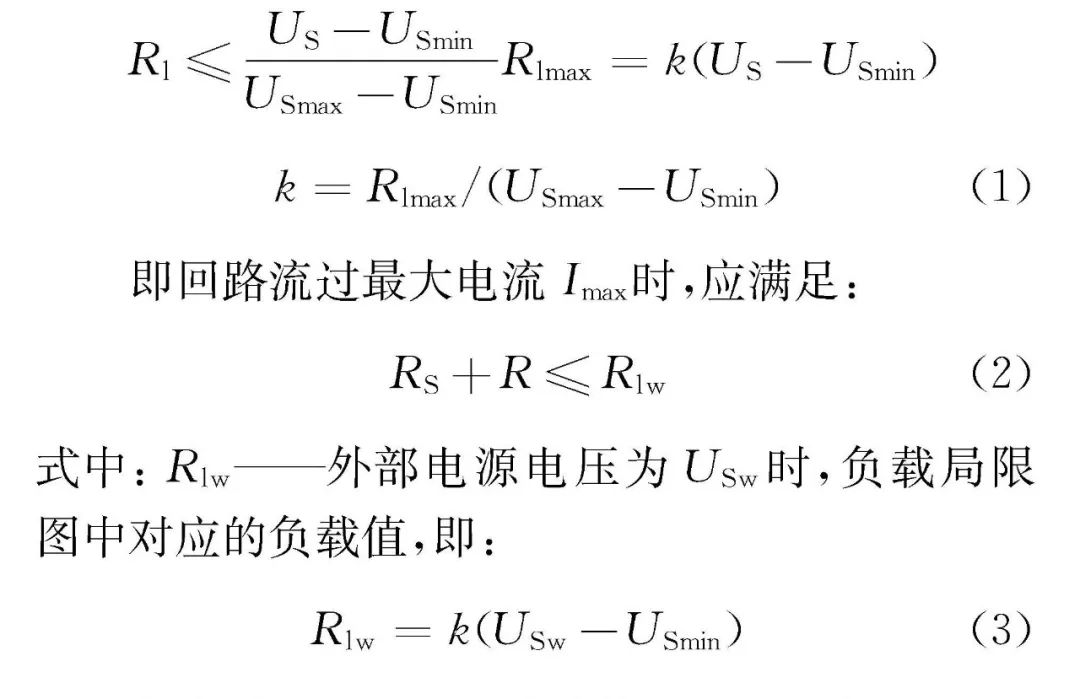
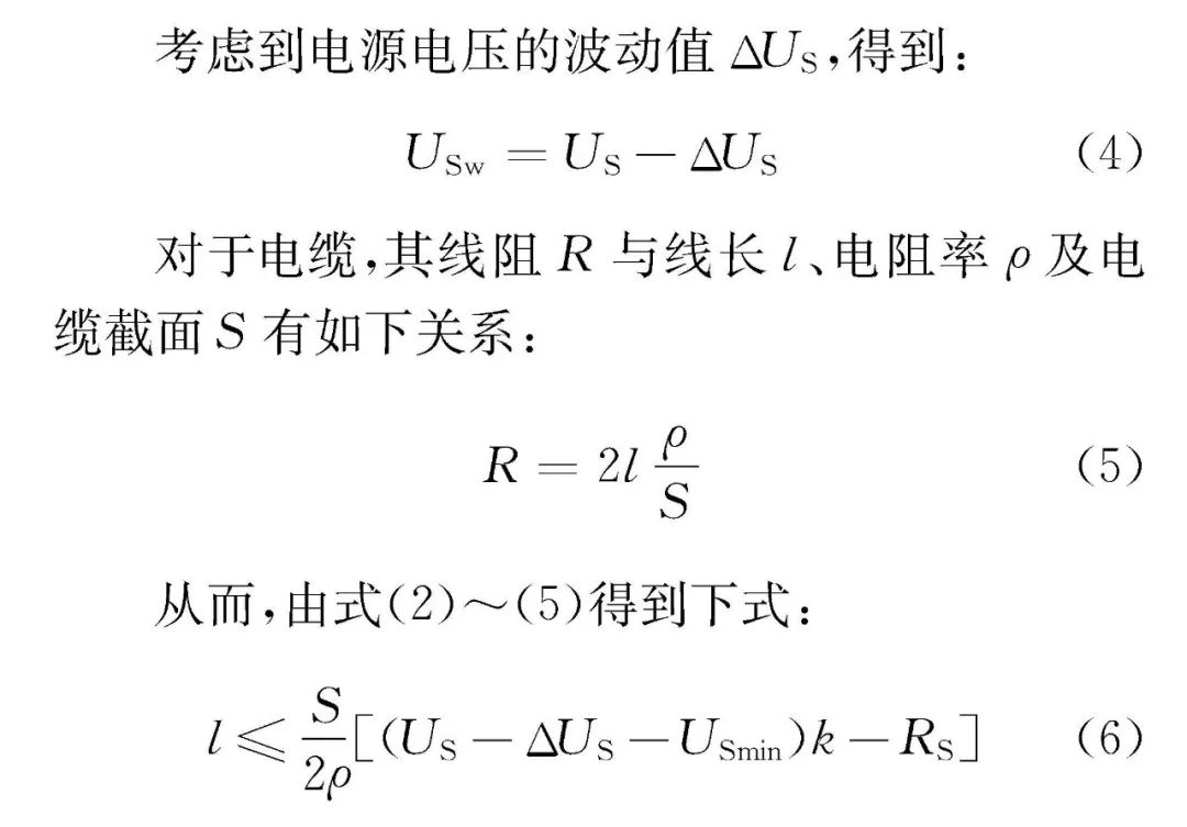
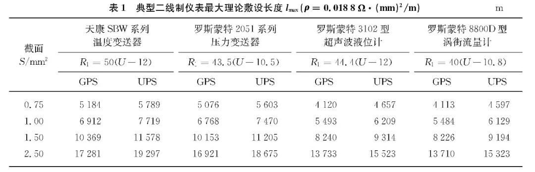
According to HG/T 20509-2000 "Instrument Power Supply Design Regulations" for DC power supply voltage requirements, when using ordinary power supply (GPS), the voltage requirement is (24 ± 1) V, that is, US = 24V, ΔUS = 1V; For the power supply (UPS), the voltage requirement is (24 ± 0.3) V, that is, US = 24V, ΔUS = 0.3V. Therefore, from equation (6), the maximum theoretical laying length is calculated for several typical two-wire instruments, as listed in Table 1.
2.2 Calculated according to design specifications
The signal transmission is not only related to the line resistance of the cable itself, but also related to the cable sense, the line capacity and the static electricity or magnetic field existing around the line laying path, which limits the transmission distance of the signal. Therefore, HG/T 20509-2000 "Instrument Power Supply Design Regulations" also clarifies the design requirements: For 24V power supply, the line pressure loss should not exceed 0.24V; for 220V power supply, the line pressure loss should not exceed 2V. According to the calculation of cable section selection in the interpretation of the article, two formulas for calculating the maximum laying length of the cable are obtained:
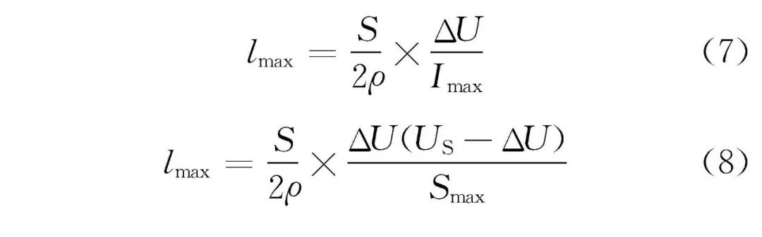
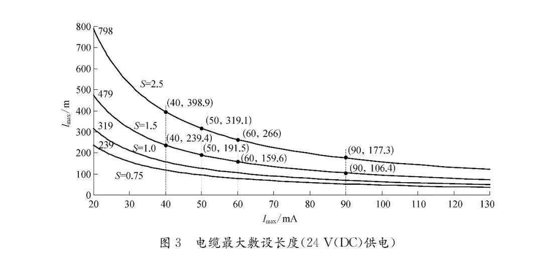
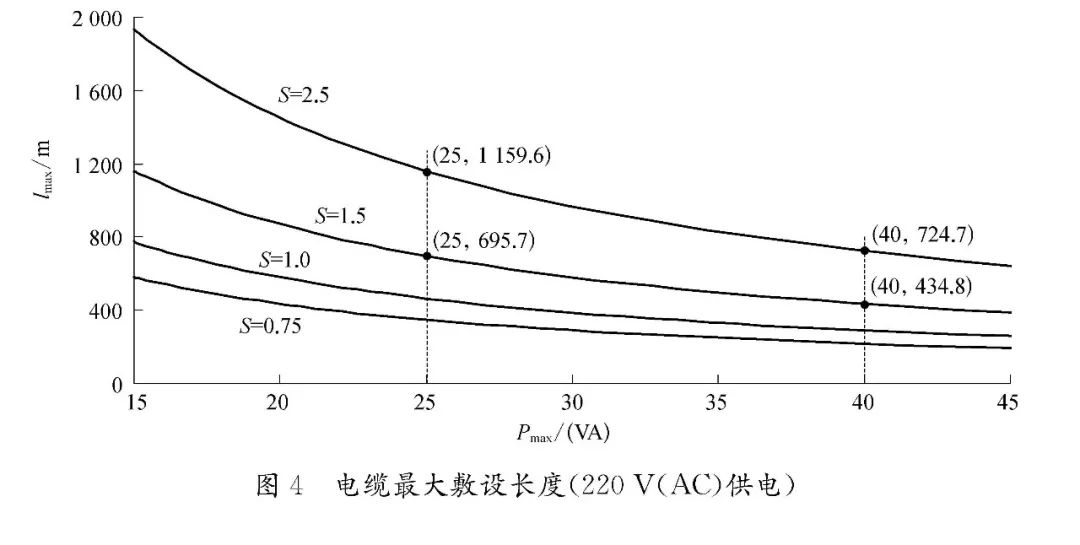
Equation (7) is used to calculate the maximum cable laying length of 24V (DC) power supply meter (including loop-powered AI, DI, DO, PI signals); formula (8) is used to calculate the maximum cable laying of 220V (AC) power supply meter The length, the corresponding function diagram is shown in Figure 3 ~ Figure 4, the abscissa is the maximum current or maximum power of the loop, the ordinate is the maximum laying length of the cable, and the four curves represent the graphs under different sections. Figure 3 Cable maximum laying length (24V (DC) power supply) Figure 4 Cable maximum laying length (220V (AC) power supply) As can be seen from Figure 3 to Figure 4, the two-wire loop power supply meter uses a cable with a section of 2.5mm2, The maximum laying length is 798m. If the meter energy consumption increases, the maximum laying length will be significantly shorter. For example, the three-wire flammable or toxic gas detector, the power supply loop current is about 90mA, and the maximum laying length of the 1.5mm2 cable is 106.4m. For the PI signal, the maximum current per channel of the card is 40 mA, the maximum laying length of the cable with a cross section of 1.5 mm2 is 239.4 m, and the maximum current per channel of the DI card is less than 20 mA, which is basically about 5 mA, so the cable can be laid. It is very long. For the DO signal, the on-site solenoid valve 24V (DC) power supply is taken as an example. The working current of the solenoid valve of the model EV8316G381V is close to 60 mA, the maximum laying length of the cable with the cross section of 1.5 mm2 is 159.6 m, and the working current of the model WBIS8316A381V solenoid valve is less than 20 mA. The maximum laying length of a 1.5mm2 cable is slightly larger than 480m. For instruments with higher power consumption, 24V (DC) power supply will lead to excessive line current and obvious line voltage drop, which can cause the instrument to fail to work normally. Therefore, 220V (AC) power supply is generally used, for example: E+H Proservo series The servo liquid level gauge has a power consumption of 40VA. If 24V (DC) power supply is used, the maximum laying length of the cable with a cross section of 1.5mm2 is less than 10m, while the 220V (AC) power supply is used, and the maximum laying length can reach 434.8m.
3 Calculation of the maximum laying length of intrinsically safe cables
The characteristics of the petrochemical project are flammable and explosive. The common types of Explosion-proof instruments are explosion-proof and intrinsically safe. The former starts from the protection of equipment to ensure that the spark generated inside the equipment does not threaten the external environment, and the latter realizes the limit from the circuit. can. For a typical intrinsically safe circuit, it should consist of three parts: on-site intrinsic safety equipment, intrinsically safe cables and safety barriers. The system loop is divided into intrinsically safe circuits and non-intrinsically safe circuits by the safety barrier: the intrinsically safe circuit is formed by connecting the intrinsically safe cable from the safety barrier to the field instrument; the circuit from the safety barrier to the DCS and to the power supply is Non-intrinsically safe circuit. Intrinsically safe circuits generally adopt parametric approval, and must meet the following five relationships (o indicates safety barrier parameters; i indicates on-site intrinsic safety equipment parameters; k indicates connection cable parameters):
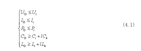
Where: Uo - open circuit voltage, that is, the maximum voltage that may be transmitted to a hazardous location under fault conditions; Io - short-circuit current, that is, the maximum current that may be transmitted to a hazardous location under fault conditions; Po - safety barrier Maximum output power; Co - associated equipment allows for external maximum capacitance; Lo - associated equipment allows for external maximum inductance; Ui - maximum acceptable voltage for intrinsically safe equipment under fault conditions; Ii - under fault conditions, this The maximum acceptable current of the equipment; Pi - the maximum acceptable power of the intrinsically safe equipment; Ci - the unprotected capacitor inside the intrinsically safe equipment; Li - the unprotected inductance inside the intrinsically safe equipment; Ck - the cable unit Distribution capacitance of length; Lk - distributed inductance per unit length of cable.
It is precisely because of the energy storage function of distributed inductance and distributed capacitance that in the event of cable failure, these energy storage will be released in the form of electric spark or thermal effect, which increases the risk of ignition and affects the intrinsic safety performance of the system. , so the maximum length of the intrinsically safe cable must be limited, ie
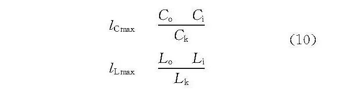
For example, the intrinsically safe detection circuit consists of Rosemount 3105 ultrasonic level gauge, Tiankang 1.5mm2 intrinsically safe cable and Emerson analog input safety barrier. The relevant parameters are: Ci=0nF, Li=0.108mH, Ck=90nF /km, Lk=0.6mH/km, Co=83nF, Lo=4.2mH. By calculation, lCmax and lLmax are 922m and 4020m respectively, so the maximum laying length of the cable after intrinsic safety calculation should be 922m.
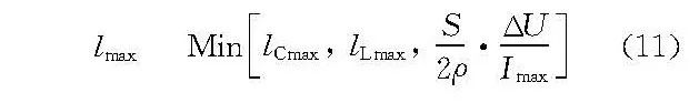
For the above example, the influence of line voltage drop should also be considered according to the specification requirements, that is, the maximum cable laying length (calculated value is 479m) is calculated according to formula (8), and combined with the intrinsic safety calculation (calculated value is 922m), the maximum cable laying length is 479m.
Therefore, through the above analysis, the maximum laying length of the intrinsically safe cable should be determined as follows:
4 Instrument cable section selection steps
Recently, the author participated in the design of a chemical project. There is a mass flow meter and a regulating valve outside the boundary area, which are used to measure and adjust the raw materials transported in the downstream plant area. The distance from the control room is about 1300m. For the AO adjustment signal, after looking at Figure 3, the cable with a cross-section of 2.5mm2 has a maximum laying length of only 798m, which is far from reaching 1300m. The adjustment effect will be difficult to guarantee, and the regulating valve is finally eliminated; The AI ​​signal, after checking, thinks that the signal transmission distance is too long, the PI and AI signals collected by the control system are not stable enough. Finally, RS485 communication is used, and the communication repeater is installed (in theory, RS485 communication can only transmit 1200m). The problem of collecting traffic signals.
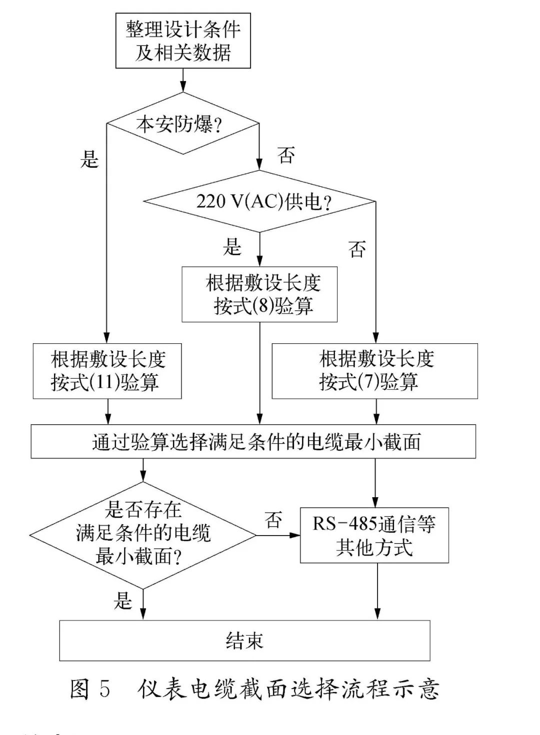
Through the above design examples, and based on the calculation of the maximum laying length of the instrument cable, the author summarizes the basic steps of the instrument cable cross-section selection, as shown in Figure 5.
5 Conclusion
With the rapid development of electronic technology, the instrument can be stably operated under low voltage conditions. In addition, the 24V (DC) power supply module can be adjusted within 24 to 28V, and can be adjusted slightly upward during use. Therefore, in actual operation, the allowable line voltage drop can be much larger than 0.24V, and it is not necessary to select the cable cross section strictly according to the design specifications. For example: By calculating the PI signal, the transmission distance of the cable passing through the cross section of 1.5mm2 should be controlled within 250m, but in the In actual use, some users use 600m.
Car Screen Protector,Car Center Console Screen Protector,Car Touchscreen Screen Protector
Shenzhen Jianjiantong Technology Co., Ltd. , https://www.tpuprotector.com