Changhong stock 118A color TV switching power supply maintenance method - Database & Sql Blog Articles
First, the circuit composition
1. Changhong clothing 118A switching power supply circuit as shown in the figure on page 34). The circuit is mainly composed of a self-oscillating circuit, a voltage stabilizing circuit, a protection circuit, a remote control DC starting and a shutdown circuit. The proud oscillation circuit is composed of the switch tube V513, the switch transformer T511, the first, the first and the seventh, the seventh, the seventh, the seventh, the seventh, the seventh, the seventh, the seventh, the seventh, the seventh, the seventh, the seventh, the seventh, the seventh, the seventh, the seventh, the seventh
2. The voltage stabilizing circuit is composed of a sampling circuit and a pulse width adjusting circuit. The sampling circuit is composed of a sticker 51, a sticker 52, a BP551, and a sticker 53. The reference circuit is composed of a voltage regulator tube VD561 and a resistor sticker 44. The comparison amplifier tube is V553. The pulse width adjusting circuit is composed of a photoelectric roller combiner VD515, a triode V511, a V512 and a bias circuit thereof.
3. The protection circuit is mainly composed of an overvoltage protection circuit, an overcurrent protection circuit and a switch protection circuit. The overvoltage protection circuit is composed of VD518, VD519, R515, paste 23 and V512. The overcurrent protection circuit is composed of R524, R526, paste 15 and V512.
The protection circuit of the switch tube mainly comprises a damping circuit composed of C516 and a sticker 25, and a soft start circuit composed of a sticker 20, a sticker 21, a R5x and a 1511, a sticker 24, a C517, and the like.
4. The remote control DC power on and off 'circuit is mainly composed of V576 and photoelectric pot table VD515.
Second, the maintenance method Changhong clothing 118A machine power maintenance method is as follows. First disconnect all the load of the switching power supply, and connect the 220V/ribbed incandescent lamp to the *130v output terminal.
1. The input of the power supply input detection switching power supply is composed of circuits such as rectification and filtering. The multimeter DC voltage file can be used to detect whether the voltage of the collector V513 is about 3 ribs V to determine whether the circuit is normal. If the voltage is 0v, it indicates that the part of the circuit is faulty, and it needs to be repaired. The main components of the fuse F501, current limiting resistor, rectifier bridge, filter capacitor C5å® are mainly detected in the circuit.
2. Detecting the intermittent oscillation part of the circuit The intermittent oscillation part is the key part of the switching power supply. Whether the switch tube can enter the switch working state is the key to realize the energy conversion between the primary and secondary of the switching transformer. It can be judged whether the operation of the entire intermittent oscillation circuit is normal by detecting whether the base of the switch tube v513 has a rectangular pulse voltage, and the method is as follows.
(1) Detecting whether the intermittent oscillator starts vibration detection method:
1 DC voltage detection method. Use the multimeter DC voltage file to detect the base voltage of the switch V513. If it is between 1 and 0.2v, it means the oscillation circuit starts.
2 "dB" voltage detection method. Use the multimeter dB to measure the voltage of the V513 base or collector with or without "6B".
2 oscilloscope observation method. Use an oscilloscope to observe the presence or absence of a rectangular pulse signal at the base or collector of the V513. Note: When measuring, the negative meter of the multimeter must be connected to the negative pole of the 300v voltage, that is, the negative pole of the filter capacitor C507.
(2) Key detection circuit: If the intermittent oscillator does not start, the following circuits should be checked.
1 Check whether the startup circuit composed of R520, R521, and R522 is open.
2 Check whether the positive feedback circuit consisting of the first and second windings of the switching transformer T511, 19, C514, 15U, and 24 is open or shorted, especially the capacitor C514.
2 Check if the voltage regulator circuit is faulty, and check V553, V511, V512, VD515 and VD516.
4 Check whether the protection circuit is faulty, focus on VD518V512, if necessary, disconnect the protection circuit for detection.
3. Detection of the output of the switching power supply VD519,
Determine whether the pulse rectifier circuit is faulty by detecting whether the output voltage of each channel is normal. Focus on the detection of rectifier diodes VD551, VD552, VD553, VD554, VD555, filter capacitors C561, C562, C563, C564, C565 and current limiting resistors.
4. The detection of the voltage regulator circuit uses a multimeter to monitor the voltage at the output, and then slightly adjusts the potentiometer in the sampling circuit to detect whether the voltage at the output changes. If the output voltage can rise, it can also drop, indicating that the voltage regulator circuit is basically normal; otherwise, there is a fault. Should focus on checking ljV553, VD515, VD56l.
Third, pay attention to matters.
1. When overhauling the switching power supply, first determine that the fault is a power failure, and not because the load is faulty, the power supply is not working properly.
2. Make sure the power control terminal of the microprocessor is powered on. 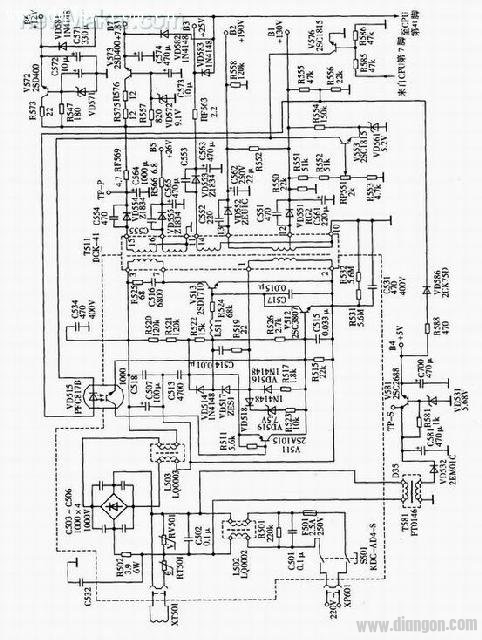
1 PCB Screw Terminal Block 2 Plug-in Terminal Block 3 PCB Spring Terminal Block 4 Barrier Terminal Block 5 Feed Through Terminal Block.
Terminal block consists of fixed terminal block (hereinafter referred to as socket) and free terminal block (hereinafter referred to as plug). The socket is fixed on the electric parts through its square (round) plate (welding method is also adopted for some), the plug is generally connected with the cable, and the plug and socket are connected by connecting nuts.
The terminal block consists of three basic units: shell, insulator and contact body.
Strictly speaking, terminal block refers to a solid device composed of an insulating base and more than one live part. Each conductive member can be used as a joint point for connecting two or more conductors (wires), and also as a tool for connecting or not connecting conductors (wires) individually. In the literal sense, the terminal block can be thought of as a wiring platform providing terminal or wire connection. The terminal block can be a combination type or a single-piece design. The combined terminal block is stacked in the way similar to the block combination, and the two ends are added with side covers and locked and fixed with screws. As for the single terminal block, the combination process mentioned above is not necessary, and it can be used alone.
Terminal Block Series
ShenZhen Antenk Electronics Co,Ltd , https://www.antenksocket.com