The measurement method and difficulty of differential mode insertion loss
Preview Questions How to measure the differential mode insertion loss of the filter with the first solution introduced earlier? How should the signal source and spectrum analyzer be connected to the filter?
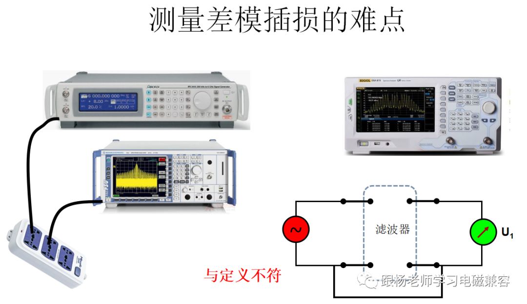
Although the definition of the differential mode insertion loss of the filter is very simple, in actual measurement, there are some details that need to be noted. If you do not pay attention, it may cause errors in the measurement data. Many designers, when using the signal source + spectrum analyzer or network analyzer to measure the differential mode insertion loss of the filter, connect the two wires (the core wire and the sheath of the coaxial cable) output by the signal source to the filter Between the two power lines, the two lines input by the spectrum analyzer (the core wire and sheath of the coaxial cable) are also connected between the two power lines of the filter, and then the measurement is performed. This method is problematic. The main problem is that the outer layer of the coaxial cable (also known as the shield) is connected to the metal shell of the device. The metal shell of the device is generally connected to the safety ground through the ground wire (yellow-green wire) in the power cord. Therefore, when the signal source and spectrum analyzer are used at the same time, their shells are connected together, as shown on the left. If you use a network analyzer program, this problem is more prominent. Because inside the instrument, the signal source module and the receiver module are already on the same ground. At this time, when we measure the differential mode insertion loss, the circuit structure in the lower right figure is formed. The situation here is clearly different from the definition of differential mode insertion loss, because a part of the circuit inside the filter is short-circuited, so the measurement result is definitely not a differential insertion loss in the true sense.
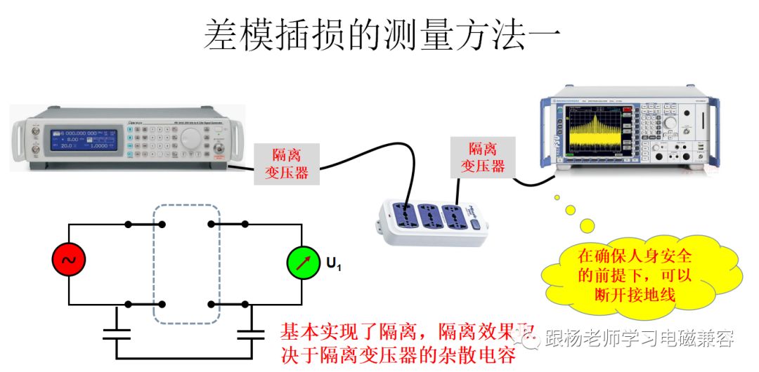
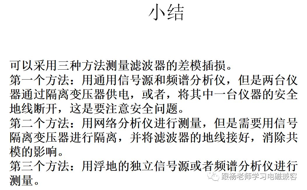
In order to be able to measure the true differential-mode insertion loss of the filter, we can install two isolation transformers on the signal source and the power line of the spectrum analyzer. In this way, the problem of the common ground of the signal source and the spectrum analyzer is avoided. The equivalent circuit diagram at this time is shown in the lower left figure. Here, there are two capacitors between the signal source and the ground line of the spectrum analyzer. This is the stray capacitance between the primary and secondary of the isolation transformer. Since the capacitor can pass high-frequency current, the differential mode insertion loss measured by this scheme may have errors in the higher frequency range. One way to solve this problem is that we directly disconnect the signal source or the safety ground wire in the spectrum analyzer. In this way, the ground wire capacitance between the two devices is greatly reduced, which can improve the accuracy of the measurement. Of course, we must pay attention to the safety of the operator. If necessary, the operator should put on insulated shoes or step on the insulated floor.
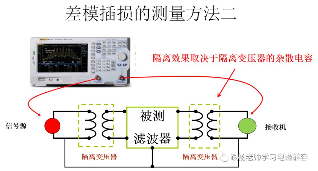
If a network analyzer is used to measure the differential mode insertion loss of the filter, it should be tested as shown in the figure. That is, the output signal of the signal source is connected between the two power lines of the filter through an isolation transformer, and the receiver is also connected between the two power lines of the filter through an isolation transformer. At this time, you can see that although the signal source and the receiver ground are still connected together, the signal injected into the filter is indeed a differential mode signal. Therefore, this method can measure the differential mode insertion loss of the filter. The problem with this method is similar to the previous problem, which is that the stray capacitance between the primary and secondary of the isolation transformer will affect the high frequency measurement accuracy. That is, when the frequency is higher, a certain common mode current will be generated, making the measured differential mode insertion loss value lower than the actual differential mode insertion loss value. One solution is to ground the filter's metal casing so that the filter can filter out this false common-mode disturbance.
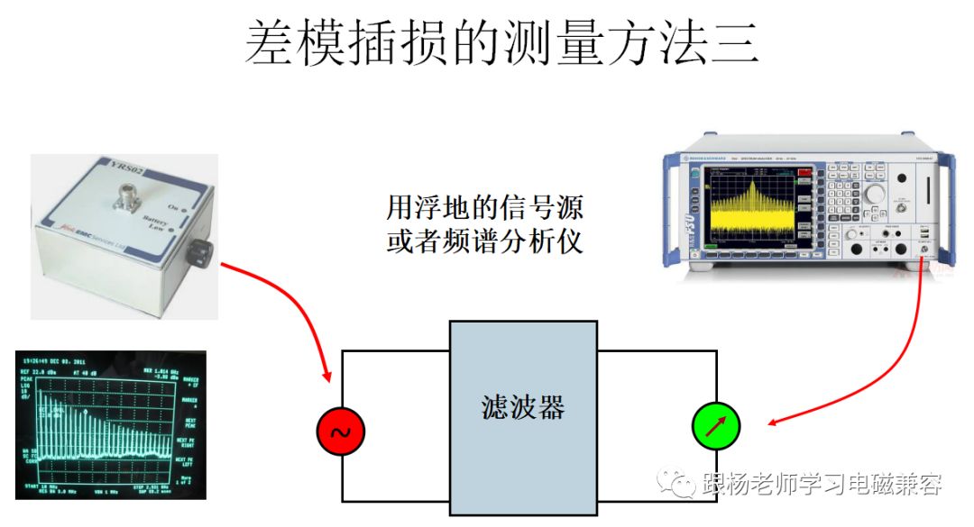
This method is to use a battery-powered comb signal generator as the signal source. Since there is no connection between this signal source and ground, it is similar to the disconnection of the safety ground of a signal source. It can be seen from the figure that this situation is exactly the same as the definition of differential mode insertion loss. Therefore, the measurement result is closest to the actual situation. In fact, if you have other battery-powered signal sources, or spectrum analyzers, you can achieve similar goals. Everyone can apply it flexibly.
Thinking questions:
In the second method, if no isolation transformer is used, what will be the difference between the measurement result and the isolation transformer?
We've been around for over 16+ years. We make sure our sound is The Best Sound.
Manufacturing high-quality products for customers according to international standards, such as CE ROHS FCC REACH UL SGS BQB etc.
wholesale earbuds, earbuds in bulk, earbuds custom, true wireless earbuds
TOPNOTCH INTERNATIONAL GROUP LIMITED , https://www.mic11.com