The working principle, characteristics and industrial application of ADRC algorithm
First, the history of PID
Before we talk about the ADRC algorithm, let's review its predecessor: PID algorithm.
H. Nyquist, who was born in Sweden in 1932 and subsequently immigrated to the United States, published a paper and used a graphical approach to determine the stability of the system. Based on it, H. W. Bode and others established a set of methods for designing feedback amplifiers in the frequency domain. This method was later used for the analysis and design of automatic control systems.
At the same time, feedback control principles began to be applied in industrial processes. In 1936, A. Callender and A. Stevenson of the United Kingdom presented the PID controller method. Since then, the PID algorithm has been formally formed. PID control is a very important control method in automatic control technology. Several decades ago, the PID controller was still mechanical, such as the air pressure controller in Figure 1.
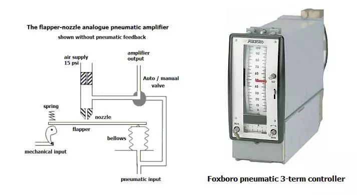
Fig. 1 Mechanical PID pressure controller
Until now, all products with "automatic control" capabilities have almost all adopted PID algorithms, ranging from weapons, aircraft and ships to home appliances, IOT equipment and toys. For example, we use daily air-conditioning, which is the use of PID algorithm to control the temperature on our expectations; mobile navigation by PID algorithm to accurately analyze the motion state; drone by PID algorithm to stabilize the flight attitude. PID is ubiquitous around us and we do our best to help humans achieve "automatic control." But unlike decades ago, with the development of computer technology, most PIDs nowadays are "soft-controlled". That is, software control is run inside the processor and the structure is greatly simplified.
Second, the principle and deficiency of PID
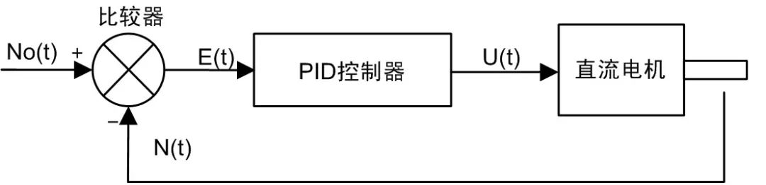
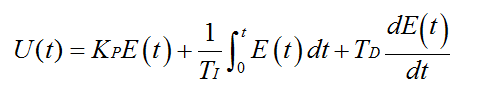
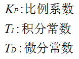
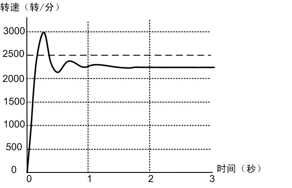
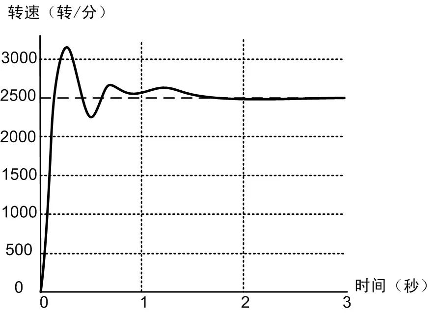
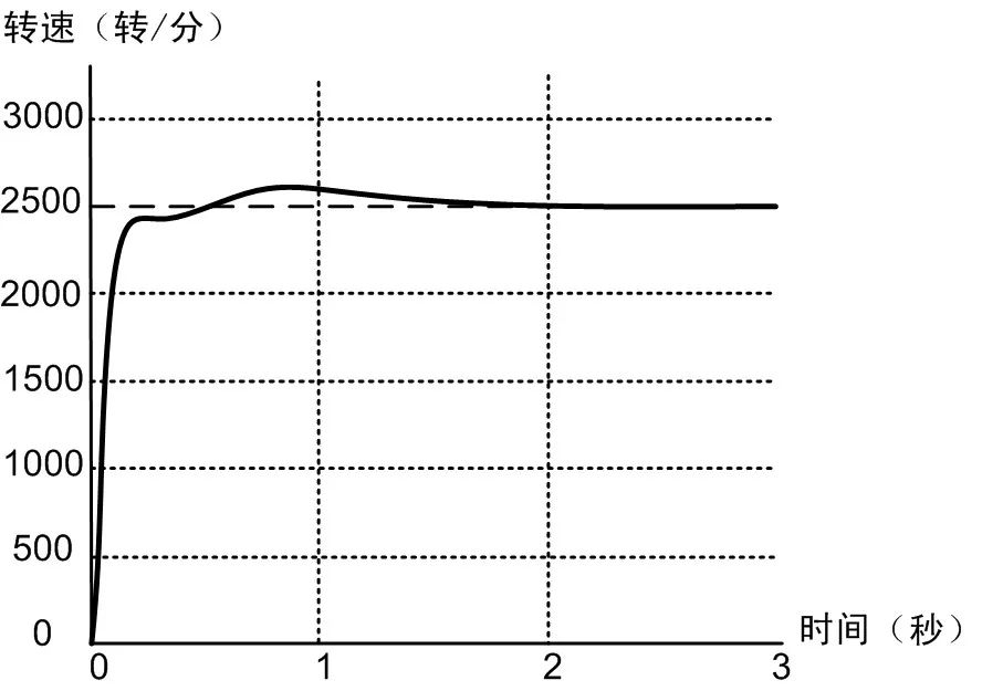
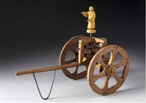
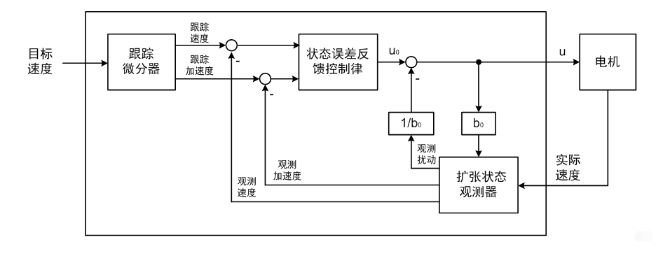
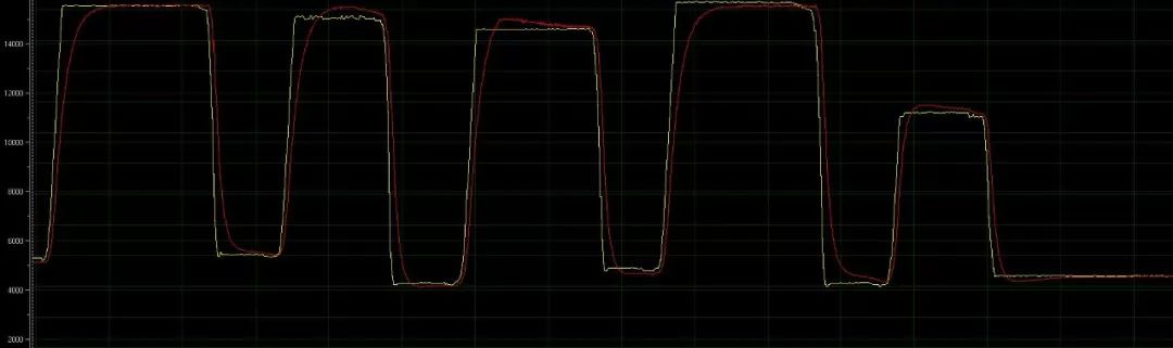
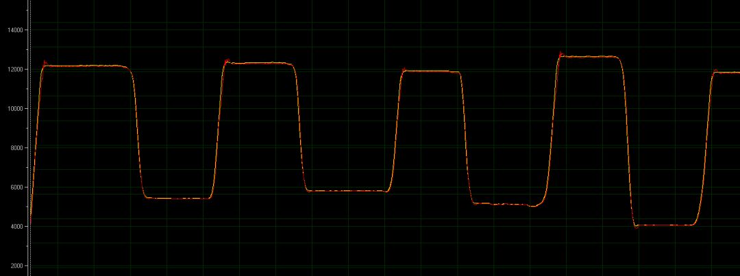
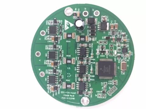
Figure 2 shows the PID speed control system for DC motors. No(t) is the desired motor target speed, N(t) is the actual speed of the motor, and U(t) is the output voltage of the PID controller. No(t) is compared with N(t), and the deviation value E(t)=No(t)-N(t) is obtained. After the PID controller calculates the output control voltage U(t), the drive motor changes the speed. . When the actual speed is too small, ie, No(t)> N(t), E(t)> 0, the PID controller increases U(t) output, the actual speed of the motor will increase; when the actual speed is too large, ie, No (t) Figure 2 DC motor PID speed control system The PID controller uses Equation 1 for calculations. There are three items on the right side of the formula, which are Proportion, Integration, and Differential. Formula 1 The role of the proportional link is to respond quickly to deviations. The larger the KP, the stronger the control ability, but the excessive KP will increase the overshoot (the amount exceeding the given value). In addition, the proportional part can reduce the static error (the deviation from the given value when stable), but it cannot be completely eliminated. Figure 3 uses the proportional link to increase the speed of the motor from zero to 2500 r/min. The lifting process is faster, but overshoot occurs and there is a static error. Figure 3 The role of proportionality The role of the integral link is to eliminate accumulated deviations (static errors). In the control process, as long as there is a deviation, the output of the integral link increases until the deviation E(t) = 0, the output may be stable at a certain value. However, the integration point will reduce the response speed and increase the overshoot. The bigger the TI, the weaker the integral action. Figure 4 is based on the proportion of the link plus the integral link, the previous static error is eliminated, the motor tends to 2500 r/min, but increased another period of overshoot. Figure 4 The role of proportional links + integral links Figure 5 uses the PID to control the motor. Each link performs its own task, and the proportion of P increases quickly. The integral link I eliminates static errors, and the differential link D suppresses overshoot. Figure 5 The role of proportional link + integral link + differential link Although PID is widely used, it has obvious deficiencies. The PID response is slow. It is necessary to wait until the error occurs before compensating for the control. If the control force is too large (the proportional coefficient KP), there is an overshoot, and if it is too small, the response is slow. PID is sensitive to environmental changes. For example, when a propeller of a drone rotates at a high speed, it is subjected to strong resistance to compressed air. The PID's force is large enough to maintain a stable speed. However, when the speed is low, the air resistance is very small and the power is strong. With the PID force, the propeller will vibrate and unstable, so another weaker PID is needed at this time. Third, the birth of ADRC Interference, or disturbance, refers to changes in the external environment of the system or changes in the internal characteristics of the system, which ultimately affect the performance of the system. For example, the propeller of the drone mentioned above, the air resistance changes with the speed, affect the stability of the motor speed, this is external disturbance; when the motor is running for a long time, the temperature rises obviously, the resistance value of the copper coil increases, the original pre There is no relationship between how much A current is estimated given how much V voltage is given, and this is an internal disturbance. Let's assume that if the world is beautiful and there are no internal or external disturbances, then for any system, just adjusting the PID parameters once can achieve the desired effect under any circumstances. However, things are counterproductive and perturbations are everywhere. How to realize the anti-disturbance effect of “he is strong by him and the breeze sweeps the hills; he crosses him horizontally and brightly shines on the big river†has always been the most important research work in autonomous engineering. The ADRC technique was developed by the late Han Jingqing researcher in reference to the classical PID control theory and was formally and systematically proposed in 1999. His inspiration comes from the guide car (also known as the Seine), which is a device used to indicate directions in ancient China. Unlike the compass, which uses geomagnetic effects, it does not use magnetism. It is a mechanical device that uses a mechanical transmission system to specify the direction. The principle is: rely on human power to drive the two-wheeled guide car to run, rely on the mechanical transmission system inside the car to transfer the differential when the two wheels to drive the car to the wooden person and the car steering direction opposite angle, so that the car The wooden man indicates the direction, no matter where the car is turned, the wooden man's hand always points in the direction set when the guide car starts. The idea that "the car was returned and the manual guide" was sublimated in the ADRC algorithm. Figure 6 Guide car Fourth, the principle of ADRC Figure 7 shows the ADRC speed control block diagram of a DC brush motor. The core of ADRC has three modules: tracking differentiator, extended state observer, and state error feedback control law. For the motor speed control, the input of the tracking differentiator is the target speed; the output is the tracking speed and the tracking acceleration, the tracking speed is equal to the target speed, and the tracking acceleration is the target acceleration. The inputs of the extended state observer are: the product of the actual speed, output voltage u, and coefficient b0; the outputs are the observed speed, observed acceleration, and observed disturbances, where the observed speed is equal to the actual speed, the observed acceleration is equal to the actual acceleration, and the observed disturbance is the system The internal and external total disturbance, which is divided by b0, subtracts the voltage u0 output by the state error feedback control law, which is the voltage u to the motor. The state error feedback control law is based on velocity error (tracking velocity - observation velocity), acceleration error (tracking acceleration - observation acceleration), and output voltage u0. If both errors are zero, then u0 is zero. The coefficient b0 is a roughly set parameter, where it indicates how many V voltages correspond to how many rotation speeds RPM. ADRC does not depend on the true relationship between voltage and speed, it only controls according to its own set b0. It thinks that the current voltage is u, and the speed should be u*b0. If the actual speed is different, the deviation is considered as disturbance (observed disturbance). It may be caused by changes in external resistance, or it may be caused by inaccurate internal motor parameter estimation. After observing the disturbance divided by b0, it is directly compensated to the u output. So the ADRC is headstrong. It doesn't need to measure disturbances specifically. "He confessed that he was evil and I'm sincere." In addition, if the system is clear at the same time: target speed and target acceleration, the tracking differentiator can be omitted and these two quantities can be directly input. Figure 7 ADRC speed control V. Characteristics of ADRC 1, almost has nothing to do with the model The ADRC is applicable to any case where the object model is completely unknown and the object model is completely grasped. As shown in FIG. 7, the relation b0 of the voltage and the speed can be roughly set. Of course, if the relationship can be accurately captured, the work intensity of ADRC will be reduced and the effect will be better. For example, we are studying, when the motor is running, serious heat, the motor internal resistance, inductance, reverse emf and other parameters have changed significantly, without injecting additional measurement signal (do not affect the motor operation), how to use AI artificial intelligence Neuron technology accurately estimates the motor parameters and reconstructs the motor model b0 so that the performance of the ADRC will be further improved. 2, responsiveness The traditional PID control must wait until the error occurs before it can compensate for the control, and the ADRC compensates the observed disturbance for the first time to the output. Furthermore, although the derivative term D in the PID has a prediction function, it only subtracts the previous error from the current error, and results in a very poor differential result. The ADRC uses a tracking differentiator to accurately track the derivative of the target value. (The tracking acceleration of Fig. 7), and the derivative of the actual value obtained by the extended state observer (the observed acceleration of Fig. 7), the two subtractions are the exact error differentials. Fig. 8 is a motor speed diagram of a certain product sold by JD.com. It uses PID-based FOC technology, the motor must stop acceleration and deceleration, the yellow line is the target speed, and the red line is the actual speed. The actual acceleration and deceleration is very fast, and the tracking effect is also OK. This effect is already the industry leader. Once upon a time we thought that if you do not change the motor, this effect can no longer be better. Figure 8 PID-based FOC But one day, as shown in Figure 9, we have replaced the PID code in the FOC directly with the ADRC, and there has been an amazing scene. The two lines of target speed and actual speed are almost coincident, there is almost no overshoot, no vibration, no static error, and acceleration and deceleration increase by more than 30%, noise reduction by 2db, and energy efficiency by 5%! Figure 9 Based on ADRC's FOC 3, ease of use Although the performance of ADRC was very high when it was first introduced, there are many parameters to be debugged and it is not easy to use. However, with the theory of Scaling and Bandwidth-Parameterization proposed, ADRC parameter adjustment becomes much simpler. For example, Zhou Ligong's ADRC library only needs to adjust the bandwidth of the extended state observer and the bandwidth of the state error feedback control law. The system can be roughly tuned. 4, flexibility ADRC is developed under the inspiration of PID. In general, as long as there is PID, it can be directly replaced by ADRC. VI. Application of ADRC Currently, ADRC has been used in many fields, such as hypersonic vehicles, magnetic levitation, superconducting particle accelerators, large radio telescopes, tank fire control systems, nuclear power plant cooling systems, etc., as well as industrial robots, servo motor drives, and drones. Systems, sweeping robots, and even site search engines, among others. Figure 10 Hypersonic Aircraft There are also Zhou Ligong's unmanned electromechanical actuators, industrial motor drivers, automotive water pump ESCs, automotive fan ESCs, brushless motor control ICs, multi-motor FOC solutions based on NXP i.MXRT, and so on. Efficient ADRC algorithm. Figure 11 S32K FOC Car ESC with Built-in ADRC Algorithm Damping and Absorption Capacitors
MKP capacitor
The products have a high share in China, and also used for INDUCTOTHERM,ELECTROTHERM,MEGATHERM,PILLAR,SUPERHEAT,ABP
, Mitsubishi electric, Fuji, the United States Yingda equipment and other
manufacturers of induction Furnace.

MKP Capacitor,MKP Capacitor 0.15UF,MKP Capacitor 20UF,MKP Capacitors 0.22UF
YANGZHOU POSITIONING TECH CO., LTD. , https://www.cnpositioning.com