Overcome the three main shortcomings of the MSI mechanism
The PCI bus has supported the MSI-X mechanism since version 3.0, and some upgrades and improvements have been made to MSI to overcome the three main defects of the MSI mechanism:
1. With the development of the system, 32 interrupt vectors are not enough for certain large-scale applications (refer to the previous article);
2. Only one target address makes static interrupt allocation difficult in the case of a multi-core CPU. If you can make each vector correspond to a different unique address, it will be much more flexible;
3. Interrupt priority confusion in some applications.
What's interesting is that MSI only supports 32 interrupt vectors, while MSI-X supports up to 2048 interrupt vectors, but the relevant registers of MSI-X take up less space in the configuration space. This is because the interrupt vector information is not directly stored here, but in a special Memory (MIMO). And through BIR (Base address Indicator Register, or BAR Index Register) to determine its specific location in MIMO. As shown below:
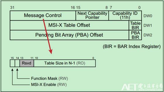
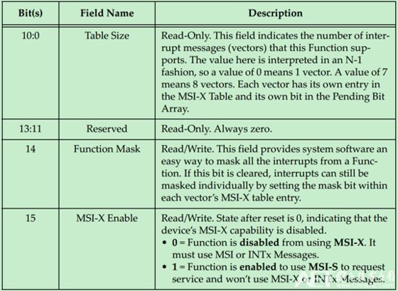
The specific description of the Message Control register is as follows:
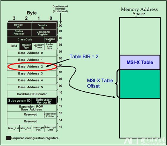
The schematic diagram of the MSI-X lookup table is as follows:
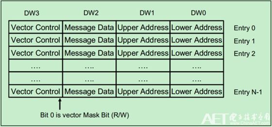
The structure diagram is as follows:
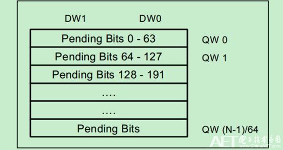
Similarly, Pending Bits is located in another Memory, the structure diagram is as follows:
Note: Both MSI and MSI-X are essentially based on Memory Write, so errors may also occur. For example, ECRC errors in PCIe, etc.
Car Phone Holder,Mobile Holder For Cars,Mobile Phone Holder For Dashboard,Mobile Phone Holder For Car Dashboard
Ningbo Luke Automotive Supplies Ltd. , https://www.nbluke.com