Principle and structure of piezoelectric knock sensor - News - Global IC Trade Starts Here Free Products
As shown in Figure 13-4, in the cantilever structure fixed at one end, if the fixed base is vibrated, it will cause free vibration. If the natural oscillator power frequency of the piezoelectric element coincides with the string of critical hydrocarbon shocks, the piezoelectric element resonates at the critical knock and the output voltage is maximized. 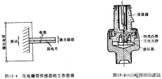
Fig. 13-5 shows the structure of a piezoelectric knock sensor in which the piezoelectric element has a shape of a thin rectangular shape and a disk shape, and Figs. 13-6 and 13-7 show the pressure of a thin rectangular shape and a circular plate shape, respectively. Electrical components. One end of the thin rectangular piezoelectric element is fixed to the housing of the sensor to form a single-ended fixed beam structure. By changing the length of the extension arm and the thickness of the arm, the natural vibration frequency can be adjusted, so that the error of the component can be controlled in a small range. As shown in Figure 13-6, the lamination structure can be used to increase the sensitivity of the sensor. The structure of the wafer-shaped element is to attach the piezoelectric ceramic sheet to the metal plate, and the metal plate is fixed on the sensor casing, so that an output signal can be obtained by using a piezoelectric piece. The natural vibration frequency of this structure cannot be adjusted after assembly, so the production error must be strictly controlled. 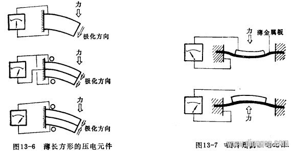
Antenk DVI Series Digital Video Interface connectors are the standard digital interface for flat panels, video graphics cards, monitors and HDTV units. This series includes DVI-D (Digital), DVI-A (Analog) and DVI-I (Integrated Digital/Audio). Their unique crossing ground blades provide high speed performance at low cost. They are available in Straight or Right Angle PCB mount receptacles and mating male cable connectors. They support a data transfer rate of 4.95Gbps with a dielectric withstanding voltage of 500VAC. Each version features our specially designed contacts which improve signal performance and a zinc alloy shield that reduces electromagnetic interference (EMI).
Digital Visual Interface Cable Connectors
DVI ConnectorWith the advent of technologies such as DVD players, high-definition televisions, and even digital cable, the need for more advanced cables and connectors has increased. Digital Visual Interface (DVI) is one response to the growing need for interconnected systems, enabling digital systems to be connected to an array of displays. Yet DVI cables and connectors can also be complicated, and may lead to confusion between High Definition Multimedia Interface (HDMI) and DVI. Although the two systems have much in common, they service different niches of digital technology.
Digital Visual Interface
Older systems aren`t necessarily outdated systems. Although DVI preceded HDMI, it`s still widely used in both business and domestic settings. DVI connectors are designed to handle digital data transmission, incorporating three transmission channels in every connector link. The maximum bandwidth for data transfer is 165 megahertz, which is enough to relay up to 165 million pixels per second. Data is encoded for effective transfer, but a single link can handle around 4.95 gigabits per second of information. Double links can handle twice that amount.
Because a DVI cable carries information over a 165 megahertz bandwidth, complete digital resolution can be obtained. Using double link connectors increases the speed of transmission, but requires another cable. However, not many devices depend solely on a double link DVI, so this technolgy can be used on an as-desired basis.
Types of DVI Connectors
There are three general categories of DVI cable connectors: DVI-Digital (DVI-D), DVI-Integrated (DVI-I), and DVI-Analog (DVI-A). However, most connectors fall into one of the first two groups.
A standard DVI Connector is 37 mm wide and has 24 pins, 12 of which are used for a single link connection. When analog is involved, four additional pins are needed to support the additional lines of an analog signal. It is not possible to cross from a digital source to an analog display or vice versa. In those instances, an integrated connector is probably the best option. There are five common types of DVI connectors.
DVI-I Single Link
This kind of connector has three rows, each with six pins. There are two contacts. Because the connector is integrated, it can be used with both analog and digital applications.
DVI-I Dual Link
A DVI-I dual link connector can also be used with both digital and analog applications, but is configured with more pins to accommodate a dual connection. There are three rows with eight pins each, as well as two contacts.
DVI-D Single Link
Specifically designed for digital applications, a DVI-D single link connector has three rows of six pins, and looks much like a DVI-I single link connector. However, a DVI-D connector has no contacts.
DVI-D Dual Link
Also made specifically for digital applications, a DVI-D dual link features more pins (three rows of eight) for dual connections. Like a DVI-D single link, a DVI-D dual link connector has no contacts.
DVI-A
This particular type of connector can only be used for analog applications, and has three rows of pins. One row has five pins, one has four pins, and the last row has three pins. Like single link connectors, a DVI-A link connector has two contacts.
Male DVI Connector
ShenZhen Antenk Electronics Co,Ltd , https://www.atkconnectors.com