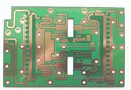
Printed circuit board soldering process and desoldering method
Master the welding temperature and time. When welding, there must be enough heat and temperature. If the temperature is too low, the solder fluidity is poor, it is easy to solidify, forming a false weld; if the temperature is too high, the solder will flow, the solder joints will not easily deposit tin, the decomposition rate of the solder will accelerate, the metal surface will accelerate oxidation, and lead to the printed circuit board The pad on the fall off. In particular, when using natural rosin as a flux, the soldering temperature is too high, it is easily oxidized and peeled off, resulting in carbonization, resulting in an imaginary weld.

First, the printed circuit board welding process
1, welding preparation
First of all, we must be familiar with the printed circuit board assembly drawings, and according to the drawings ingredients, check the components of the model, specifications and quantity meet the requirements of the drawings, and do a good job pre-assembly component lead molding and other preparations.
2, welding sequence
The order of component assembly and welding is: resistors, capacitors, diodes, transistors, integrated circuits, high-power tubes, and other components are first small and large.
3, the welding requirements of components
(1) Resistor welding
According to the figure, the resistor is accurately fitted to the specified position. The requirements are marked upward and the words are consistent. After loading the same specification, install another specification and try to make the resistors consistent. After soldering, the excess pins exposed on the surface of the printed circuit board are trimmed.
(2) capacitor welding
Put the capacitor as shown in the figure, and note that there are polar capacitors whose "+" and "-" can't be connected incorrectly. The direction of the mark on the capacitor should be easy to see. Glass glaze capacitors, organic dielectric capacitors, ceramic capacitors, and finally electrolytic capacitors are installed first.
(3) Welding of diodes
Diode welding should pay attention to the following points: First, pay attention to the polarity of the anode and cathode, can not be installed wrong; Second, the model mark should be easy to see; Third, when welding vertical diodes, the welding time for the shortest lead can not exceed 2S.
(4) Triode Welding
Note that the three lead positions of e, b and c are correctly connected; the welding time is as short as possible, and the lead pin is clamped with tweezers during welding to facilitate heat dissipation. When welding high-power triodes, if you need to install heat sinks, the contact surface should be flat, smooth and then tightened. If you need to add insulation film, do not forget to add films. When connecting the pins and the circuit board, use plastic wires.
(5) Integrated circuit welding
First, according to the requirements of the drawings, check whether the model and pin position meet the requirements. When soldering, first weld the two pins of the edge to position them, and then weld one by one from top to bottom from left to right.
For capacitors, diodes, and triodes exposed on the printed circuit board surface, extra pins must be trimmed.
Second, the method of desoldering
In the process of commissioning, repair, or replacement of components due to welding errors, they need to be removed. Improper desoldering methods often result in damage to components, cracking of printed conductors, or detachment of pads. Good de-soldering technology can ensure smooth debugging and maintenance work and avoid increasing product failure rate due to the failure to replace components.
Ordinary components demolition:
1) Select the right medical hollow needle to remove welding
2) Desoldering with copper braid
3) Dismantle with airbag suction
4) Use special desoldering electric iron to remove welding
5) Use soldering iron to remove welding
1.50mm Wire To Board Connectors
1.50mm Wire To Board Connectors:Line to board has rubber shell, terminal and needle holder.
The wire to board connector connects the wires to the printed circuit board (PCB) to realize the connection between circuits. Our line to board connectors focus on flexibility and reliability, suitable for small size plug-in and safe termination, and are equipped with friction locking mechanism or full locking mechanism. Our lcedi connectors provide excellent performance in both low voltage differential signaling (LVDS) and embedded DisplayPort (EDP) applications. Our economical power supply (EP) connectors have up to 12 locations, so your product can reliably deliver power to circuit boards when space is limited. We offer PCB male terminals with multiple or single connection types, including bolt mounting, printed circuit mounting, wire crimping, testing, soldering, and mounting frames for quick disconnect applications.
1.50mm Wire To Board Connectors
ShenZhen Antenk Electronics Co,Ltd , https://www.antenkelec.com