Central air conditioning energy efficiency management system based on P87LPC764 single chip microcomputer
l Introduction
This article refers to the address: http://
The central air conditioning system mainly consists of a chiller, a cooling water circulation system, a chilled water circulation system, a fan coil system and a cooling water tower. The refrigerator compresses the refrigerant into a liquid state through a compressor, and then exchanges heat with the chilled water in the evaporator to cool the chilled water. The chilled water pump sends the chilled water to the cooling coil of each fan tuyere, and the fan blows the cold air to cool down. the goal of. In the system, the cold pump, cooling pump, and water tower fan inverter adopt open-loop control, which is adjusted by maintenance personnel according to different seasons and load changes. Heat exchangers and circulating fans are installed in each room to control the fans. The speed of rotation changes the amount of heat exchange to achieve the purpose of adjusting the room temperature.
The common control method is to control in the "high, medium, low, off" binning mode. The disadvantage is that the temperature of the room needs to be manually adjusted. Changes in various environmental factors often make people feel uncomfortable. The fan speed control scheme adopts frequency converter speed control, which effectively solves the above problems and achieves the purpose of automatic adjustment of indoor temperature, which greatly saves energy.
2 Central air conditioning energy efficiency management system overall control parameters principle
The temperature required for indoor control is set to Tsv, the outlet temperature of the bellows is Tw, the current indoor ambient temperature is measured as Tpv, the outdoor temperature is T0, the indoor dispersion (suction) thermal coefficient is Kv, and the specific heat capacity is C. The air flow generated by the rotation of the fan is q, the specific heat capacity is Cp, the flow rate q is proportional to the rotational speed n of the fan, and the proportional coefficient is Kc. According to the dynamic energy balance principle, it is obtained:
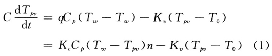
It can be seen from the formula (1) that the main factors affecting the indoor temperature are the bellows outlet temperature Tw, the indoor ambient temperature Tpv, the indoor dispersion (suction) heat coefficient Kv, and the circulating fan rotational speed n. Kv is determined by indoor ambient temperature, outdoor temperature and room sealing and heat insulation. Therefore, selecting the speed of the circulating fan as the control parameter is the best parameter for adjusting the room temperature to achieve energy saving.
3 Central air conditioning energy efficiency management system performance characteristics
The central air conditioning energy efficiency management system mainly has the following characteristics:
(1) The power supply is 220 VAC, and the power consumption is less than 5 W;
(2) Indoor temperature LCD liquid crystal display, temperature range is 5~30°C; accuracy is 1°C, and LCD8-10 display real-time temperature value;
(3) Control voltage output function, the voltage output resolution is 10 bits, the output voltage range is O~5 V, and the PID control period is 5 min;
(4) Running time accumulation function, LCD1 is displayed in 4 digits, 5, 6 digits is displayed in minutes, and is automatically stored once every hour. Each stop running time is automatically stored in E2PROM, and each time it is automatically read from E2PROM. The stored time value is sent to the LCD display;
(5) On-site programming function, the indoor target temperature, control period and adjustment range are randomly set on the site;
(6) Man-machine interface function, 10-digit LCD digital display, 5 operation keys are MOD, UP, DOWN, ENTER, SlTART/END. The sound prompt function, the button valid buzzer sounds 1 sound, the input setting data valid buzzer sounds 2 sounds, the input setting data error buzzer sounds 3 sounds, the equipment fault alarm buzzer sounds 5 sounds.
4 system hardware principle and design
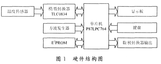
The hardware structure of the central air conditioning energy efficiency management system is shown in Figure 1. The TCl047A linear voltage output temperature sensor is selected. The output signal (temperature measurement signal) is sent to the analog/digital converter TLC0834 through the integrated operational amplifier LM358 for A/D sampling. The analog signal is sent through the bus after the A/D changed digital signal. Go to the microcontroller for processing. After processing, the control signal is output to the digital-to-analog converter TLC5615 to realize the control of the inverter power, which greatly saves energy. The display data is sent to the LCD621 through the bus. The keyboard uses the keyboard interrupt mode for interrupt processing. The relay controls the start and stop of the fan through the pull-in and disconnection. The E2PROM 24C02 is used to store the temperature setting value and the PID parameter. It can be seen that compared with similar products, the hardware of the product is simple, realizes human-machine exchange, requires few devices, and can be realized at a very low cost.
4.1 Temperature detection link
4.1.1 Overview of TCl047A
The TCl047A is a linear voltage output temperature sensor whose output voltage is proportional to the measured temperature. It accurately measures temperatures in the range of 40 to +125 °C. At the same time, the operating voltage range of the TCl047A is 2.5 to 5.5 V. Typical output voltages for this type of temperature sensor are 100 mV at 40 °C, 500 mV at 0 °C, 750 mV at +25 °C, and 1.75 V at +125 °C. The output voltage slope of 10 mV/°C allows accurate measurement of temperatures over a wide temperature range. The TCl047A is available in a 3-lead SOT-23B package for space-critical temperature measurement applications.
4.1.2 Overview of TLC0834
The TLC0834 is an 8-bit successive approximation analog-to-digital converter from TI that features an input configurable multichannel multiplexer and serial input/output. Its multiplexers can be configured as single-ended or differential inputs by software or as pseudo-differential inputs. In addition, the input reference voltage can be adjusted. It allows for arbitrarily small analog voltage coding intervals at full 8-bit resolution. Because the TLC0834 uses a serial input structure, the package size is small, saving 51 series of microcontroller I / 0 resources, the price is also moderate. Its main features are as follows: 8-bit resolution; easy to interface with the microprocessor or independent use; full-scale operation; address logic multiplexer strobe 4 input channels; single 5 V power supply, input range is O ~ 5 V; When the input and output are compatible with TTL and CMOS levels with a clock frequency of 250 kHz, the conversion time is 32μs; it can be replaced with National Semiconductor's ADC0834 and ADC0838, but it does not have a Zener regulator network internally; The adjustment error is ±1 LSB.
4.2 Signal Processing Unit P87LPC764 8-bit 0TP Microcontroller
The P87LPC764 series of single-chip microcomputers are developed by Philips to meet the needs of low-cost, high-integration applications. The chip uses an accelerated 51 core. At the same clock frequency, its speed is twice that of the standard 51, including A/D, UART serial port. With its own oscillator, I2C bus interface, etc., can meet many aspects of performance requirements.
P87LPC764 includes central processing unit, 128 B internal data memory RAM, 4 kB OTP program memory, 15 I/O ports and 1 input port, 2 16-bit independent timer/counter for overflow trigger function, 8 keyboards Interrupt input and two external interrupt inputs. In addition, P87LPC764 also has power-on reset, idle power-down mode, and low-level interrupt wake-up function. In power-down mode, the current is only 1μA. If the on-chip oscillator is selected, no external components are required, and only the positive power supply and ground wire can be connected. A separate watchdog oscillator circuit that detects the operating state of the clock source. 32 B user code area can be used to store serial code and setting parameters, 4 interrupt priority levels.
5 system software design
The main program flow chart is shown in Figure 2. The user-friendly design allows the user to operate intelligently without having to do anything. When the power is turned on, the system enters the initialization program and initializes the MCU P87LPC764, LCD, and E2PROM respectively. The indoor temperature is collected and displayed in real time, and then the microcontroller is in a sleep state, waiting for an external interrupt or a keyboard interrupt generated by the square wave generator.
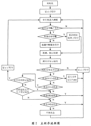
When the square wave generator is every O. When 5 s generates 1 interrupt to wake up the MCU, the main program calls the accumulated time processing subroutine to accumulate the system running time, and automatically stores the time data into the E2PROM every hour.
After the keyboard is interrupted, the program enters the key interrupt service program and performs the key operation function to complete the setting of the working mode, control cycle and adjustment range. After the execution of the interrupt program is completed, the system measures the real-time temperature and displays the temperature. The system has a total of 5 temperature control states, square wave generators per O. After 5 s generates an external interrupt, the system queries the system temperature control status and adjusts accordingly according to the corresponding status.
State 0 is not activated, indicating that the host has just started running. The difference between the indoor temperature and the target temperature may be large. At this time, the system runs at full power for 5 min, so that the indoor temperature reaches the target temperature in the shortest time.
The state l is the startup state. At this time, it is necessary to judge the magnitude relationship between the sampled indoor temperature and the user-set temperature value. When the indoor sampling temperature is greater than the user-set temperature, the system enters the state 2 speed-up state to improve the output of the digital-to-analog converter. The voltage, thus achieving increased motor power and accelerated cooling. When the indoor sampling temperature is lower than the user-set temperature, the system enters the state 3 deceleration state, reducing the output voltage of the digital-to-analog converter, thereby reducing the motor power target. When the indoor sampling temperature is equal to the user setting, the system enters the equilibrium state and keeps the motor power unchanged. Therefore, the room temperature is maintained at a constant temperature desired by the user, which makes people feel comfortable and satisfied, and more importantly, the energy saving effect is as high as 30% or more.
6 Conclusion
After debugging, the program has a good effect in practical applications. In the actual test, there are 2 points worth noting:
(1) Industrial collection requires sensitivity based on accuracy, but these two points are sometimes conflicting. In practical applications, generally 64 acquisitions can guarantee accuracy and sensitivity.
(2) Since the compared parameters can be stored in the E2PROM, as long as the circuit is slightly modified, it can be applied to other occasions and industrial and mining requirements. Therefore, this low-cost, high-precision temperature-controlled energy-saving device is more competitive, and is beneficial to both buyers and sellers.
The system is controlled by P87LPC764 single-chip microcomputer, with few peripheral circuits, stable system, strong function, convenient operation, low cost and worthy of promotion.
Easy Electronic Technology Co.,Ltd , https://www.pcelectronicgroup.com