LCR digital bridge purchase method _lcr digital bridge function introduction
LCR digital bridge belongs to the category of cable electrical performance testing. It is different from combustion testing machine, tensile testing machine, etc. When it comes to digital bridges, the traditional sayings are instruments that can measure inductance, capacitance, resistance and impedance, but with The continuous advancement of society, especially the development of modern analog and digital technologies, the early bridge impedance measurement has also been eliminated, but the name of the LCR digital bridge has been used until now, but the real reason for its name is the bridge Internally installed microprocessor, today, Yunuo Xiaobian wants to share with you the working principle of LCR digital bridge:
L: Inductance (to commemorate physicist Heinrich Lenz), C: Capacitor, R: Resistance, digital bridge is an instrument capable of measuring inductance, capacitance, resistance, impedance, and the digital bridge is measured by impedance. The parameters of the component include the AC resistance R, the inductance L and its quality factor Q, the capacitance C and its dissipation factor D. Therefore, the digital bridge is often referred to as a digital LCR meter. The measurement frequency is from the power frequency to about 100 kHz. The basic measurement error is 0.02%, which is generally around 0.1%.
The principle of the digital bridge is shown in the figure. In the figure, the DUT is the device under test, its impedance is represented by Zx, and Rr is a standard resistor. The switch can measure the voltages Ux and Ur of the two, respectively, so there is the following formula:
Zx=Ux/Ix=Rr*Ux/Ur
This formula is a phasor relationship. If a phase sensitive detector (PSD) is used to measure the in-phase component and the quadrature component of Ux and Ur corresponding to a certain reference phasor, respectively, and then convert it into a digital quantity by an analog-to-digital conversion (A/D), and then The complex value and the reactance value of the measured impedance Zx are obtained by a computer performing a complex operation.
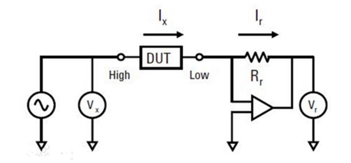
As can be seen from the circuit and working principle in the figure, the digital bridge only inherits the traditional name of the bridge. In fact, it has lost the form of the traditional classic AC bridge, but at a higher level back to Ohm's law-based ammeter, voltmeter circuit and principle.
The digital bridge can be used for the verification and transmission of impedance gauges by the metrology test department, as well as the conventional measurement of impedance components in the general sector. Many digital bridges have a standard interface that automatically divides the component under test according to the accuracy of the measured value. It can also be directly connected to the automatic test system for automatic inspection of the product on the component production line to achieve the production process. QC.
Choosing the main aspects of LCR digital bridge careA) Measurement accuracy
Measurement accuracy is the main indicator of instrument performance. Knowing exactly the accuracy of the instrument you need is the key to accurately evaluating the pros and cons of the component. In general, the accuracy of the instrument should be 3-5 times higher than the technical specifications of the measuring component. More importantly. Usually instrument samples or other promotional materials give the highest accuracy under certain conditions. This is the most confusing thing. It should be understood that the impedance of the measured component at the measurement frequency is the corresponding instrument. Whether the accuracy meets the measurement requirements.
B) Test signal frequency and level
The test frequency and level are the primary parameters to be determined by component detection, and are the most important content reflecting the correlation of component elements. It is extremely important for the correct selection of LCR bridges.
C) Instrument price
Before purchasing an instrument, you should determine the performance and functionality of the instrument and estimate the purchase budget. Generally, instrument pricing is determined based on factors such as frequency accuracy and performance. After several years of efforts, the gap between the technology and process level of domestic LCR bridges and foreign advanced levels has been greatly shortened. Domestically produced instruments of the same grade have a price difference of 2-6 times compared with imports.
How to choose LCR digital bridgea) The LCR digital bridge can measure L, C or R using two equivalent circuit modes: parallel and series, as shown in the following table:
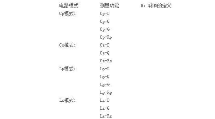
b) Selection of circuit mode of capacitor
Small Capacitors:: Small capacitors can generate large reactance, which means that the effect of shunt resistance (Rp) is significantly greater than the effect of series resistance (Rs). Compared with the capacitive reactance, the influence of the resistance value represented by Rs is negligible, so the parallel circuit mode (Cp-D or Cp-G) should be used.
Large capacitance: Measurement involves large capacitance values ​​(low impedance), then Rs is more important than Rp, so series circuit mode (Cs-D or Cs-Q) should be used.
c) Selection of circuit mode of the inductor
Large inductance: The reactance at a given frequency is relatively large (compared to the reactance of a small inductor), so parallel resistance is more important than series resistance. Therefore, the parallel equivalent circuit mode (Lp-D, Lp-Q or Lp-G) is more suitable.
Small inductance: For small inductance values, the reactance becomes relatively small (compared to the reactance of a large inductor), so the series resistance component is more important. Therefore, the series equivalent circuit mode (Ls-D or Ls-Q) is more suitable.
d) The following rule of thumb can be used to select the circuit mode based on the capacitance or inductance impedance:
The impedance is greater than about 10kΩ using the parallel circuit mode.
The impedance is less than about 10 Ω using the series circuit mode.
The impedance is chosen between the two values ​​according to the recommendations of the capacitor or inductor manufacturer.
LCR digital bridge selection table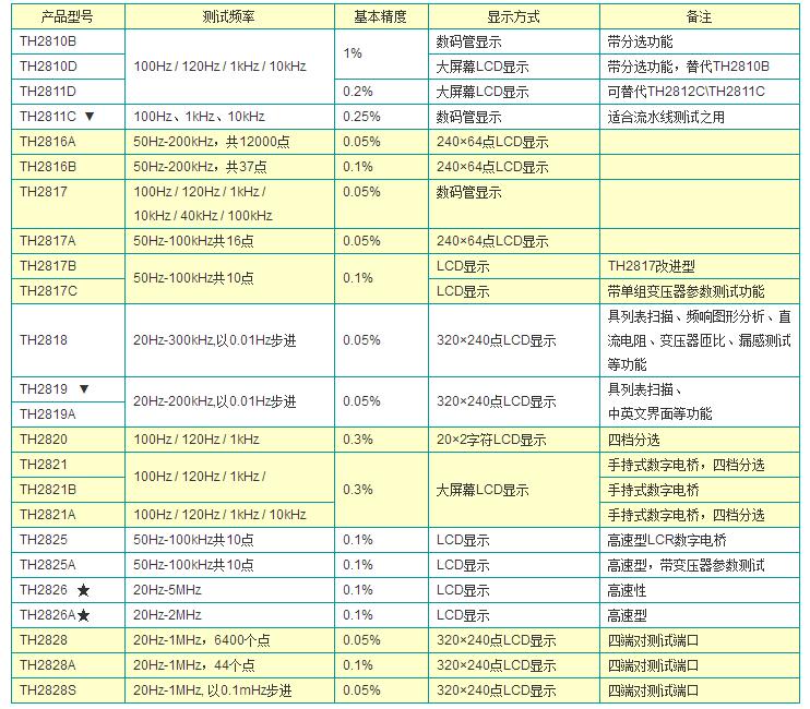
The LCR bridge using a microprocessor is called an LCR digital bridge. The average user also calls these: LCR tester, LCR bridge, LCR meter, LCRMeter and so on. A large number of electronic components can be accurately measured: a wide range of measurement target semiconductor components: impedance parameters measurement of capacitors, inductors, magnetic cores, resistors, transformers, chip components and network components. Other components: impedance evaluation of printed circuit boards, relays, switches, cables, batteries, etc.
Dielectric materials: Loss angle evaluation of the dielectric constant of plastics, ceramics and other materials.
Magnetic Materials: Assessment of magnetic permeability and loss angle of ferrite, amorphous and other magnetic materials. Semiconductor materials: dielectric constant, conductivity and CV characteristics of semiconductor materials.
Liquid crystal material: CV characteristics such as a dielectric constant and a spring constant of a liquid crystal cell. Multi-component, material property measurement capability Multi-parameter mixed display function Multi-parameter simultaneous display can meet the comprehensive observation and evaluation requirements of various distributed parameters of complex components without having to repeatedly switch measurement parameters. The inductor L and its DC resistance DCR can simultaneously measure the display, significantly improving the efficiency of the inductor measurement. It reveals the various characteristics of inductive devices using internal/external DC offsets, combined with various scan test functions, to accurately analyze the performance of magnetic materials and inductive devices. Through the bias current superposition test function, it is possible to accurately measure the low current superposition performance of high frequency inductive devices, communication transformers, and filters. Using an external current stacking device, the bias current can be up to 40A for accurate analysis of high power, high current inductive devices. Accurate ceramic capacitance measurements of 1kHz and 1MHz are the primary test frequencies for ceramic materials and capacitors.
Ceramic capacitors are characterized by low loss values, while the AC signal applied by their capacity and loss produces significant changes. The instrument has broadband testing capability and provides good accuracy, six-bit resolution and automatic level control (ALC) to meet the reliable and accurate testing needs of ceramic materials and capacitors. Capacitance Characteristics of Liquid Crystal Cell Measurement Capacitance-voltage (C-Vac) characteristics are the main method for evaluating the performance of liquid crystal materials. A problem encountered by conventional instruments for measuring the C-Vac characteristics of liquid crystal cells is that the maximum test voltage is insufficient. The extended measurement option provides programmable test signal levels of 1% resolution and up to 20Vms, enabling it to measure capacitance characteristics of liquid crystal materials under optimal conditions. Measurement of Semiconductor Materials and Components When evaluating MOS-type semiconductor fabrication processes, parameters such as oxide layer capacitance and substrate impurity density are required, which can be derived from measurements of C-Vdc characteristics. The C-VDC characteristic can be easily measured by the provided DC source combined with various scanning functions. In order to test semiconductor devices on wafers, extension cables and probes are required, and the instrument's 1m/2m/4m extension cable option minimizes cable extension errors. The distributed capacitance of various diodes, transistors, and MOS tubes is also the test content of this instrument.
The TPU materials type raw cable jacket can guarantee longer lifetime and quality. Coiled cable can be used to carry electrical currents as well as data and signal for telecommunications applications. This versatility makes coil cords ideal for use in environments that are often too rough for non-coiled cable.
It has the ability to extend beyond the natural length at rest, which can be a real space-saving feature. These cords are flexible beyond simple extending and retracting in that they can also be pulled, bent, and twisted without experiencing the metal fatigue of a straight cable.
Flex Coiled Cable Assembly, coiled cable harness, flex coiled wiring cable,High Quality Electrical Wire Harness,light-duty coiled cables
ETOP WIREHARNESS LIMITED , https://www.oemmoldedcables.com