Design of DS-CDMA System for Wireless Transmission of Train Internet
Design of DS-CDMA System for Wireless Transmission of Train Internet
Railway is the most important and important means of transportation in China. China's railway trains send approximately 1.6 billion passengers every year. In order to alleviate the lack of railway transportation capacity, the four main lines of Beijing-Guangzhou, Beijing-Shanghai, Beijing-Ha, and Longhai have been gradually electrified. The transformation of railway electrification can increase the speed of trains and also has a certain impact on train communication.
First of all, the electric contact network of the electrified railway is only 6 meters from the ground and only about 1 meter from the top of the train car, but the voltage is as high as 27,500 volts. The powerful electromagnetic field caused interference to the radio signals of communication. Secondly, the high-speed operation of the train brings Doppler frequency shift to the wireless transmission signal, and the train car itself has a certain shielding effect on the wireless transmission signal. The influence of these many factors caused the noise of the wireless transmission signal during the train running to be large, the reception was difficult, and even the communication was interrupted in severe cases.
Therefore, how to overcome these difficulties in reality by designing and implementing an effective wireless transmission system of high-speed railway interconnection network to provide broadband wireless access services for passengers in the carriage during high-speed movement has become an urgent problem to be solved. problem.
This article aims at the special situation of many railway points, long lines, scattered stations, and linear distribution. It makes full use of the existing SDH cable transmission equipment SBS622 and moves through the design of the base station fixed on the railway station and the high-speed train. The wireless interface between the stations and the technology of the top disc antenna have realized the DS-CDMA wireless transmission system of the railway high-speed train interconnection network.
Design of SDH access network transmission channel
In this design, we mainly use the SDH access network to provide the transmission channel. The optical synchronous digital network SDH is a general technical system suitable not only for optical fiber but also for microwave and satellite transmission. It has a unified network node interface NNI all over the world, which simplifies the signal intercommunication and signal transmission, multiplexing, cross-connection and exchange process; and has a set of standardized information structure level and block frame structure, allowing a rich arrangement of The overhead bits are used for network operation, management, and maintenance OAM. Its basic network unit has synchronous optical cable line system, synchronous multiplexer SM, add-drop multiplexer ADM and synchronous digital cross-connect system. Its special multiplexing structure allows existing traditional digital multiplexing systems to enter its frame structure; and it uses a large number of software for network configuration and control, making it easier to add new functions and new features.
In order to ensure the reliability of communication, the transmission of railway communication signals adopts a ring structure, and the protection is implemented at the transmission medium layer, multiplexing section layer and channel layer. The specific implementation scheme is shown in Figure 1. Show.
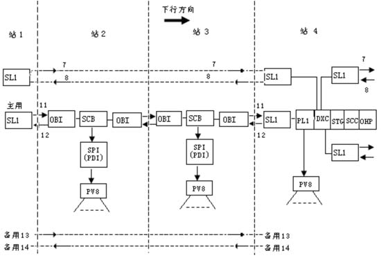
The main business of the access network is to transmit from the two optical fibers of 11 and 12, while the two optical fibers of 7 and 8 realize the loopback of the business. When 11 and 12 are interrupted, the software system automatically enables 7, 8 to realize the uninterrupted transmission of services.
In Figure 1, PL1 is a tributary board, which is an electrical port tributary board with a rate of 16 * 2M. It mainly completes the line reception, transmission and conversion of E1 signals and the timing extraction of 2M branch clock signals, realizes the mapping and de-mapping of 2M signals via TUG-2 to VC-4, and at the same time collects branch alarm reports and according to the line alarm status Complete channel protection. DXC stands for digital cross-connect board. One DXC can complete the full cross-connect of the upper and lower services in any direction on the four circuit boards. Use the low-order channel (VC-12) and high-order channel (VC-3, VC-4) provided by the digital cross-connect function to achieve business protection. STG stands for clock board, SCC board is the system control and communication board of SDH equipment, it is responsible for the management and control of the synchronization equipment and communication between each other in SDH equipment. The OHP board is an overhead processing board, which is connected to the line unit and the branch unit board, and completes the extraction and insertion of E1, E2, and F1 overhead bytes and other data bytes in the line direction and the branch direction. The most important thing is to provide Official telephone channel.
The SL1 board is a 1 * 622M optical port tributary board, which completes the transmission and reception of line signals. SCB is a dedicated processing board for small stations. It includes timing unit function (STG), overhead processing unit function (OHP), main control unit function (SCC) and cross-connect function (DXC). It is a comprehensive processing board. The SPI board is an electrical port tributary board, in which the SPI (S) capacity is 4 * 2M and the SPI (D) capacity is 8 * 2M. PDI is also an electrical port tributary board, where PD (S) only has a capacity of 16 * 2M, and PDI (D) has a capacity of 32 * 2M. The OBI board is also called 2/1 * 622M synchronous circuit optical interface board, and its transmission distance is slightly shorter than the SL1's 70KM, about 30KM. The PV8 board mainly realizes the function of a local device. It processes the signals sent by the local device to the main control board (digital cross-board) and sends the signals sent from the main control board (digital cross-board) to the local device after processing. .
In this design, the SBS 622 transmission equipment we used can provide us with a 622Mb / s data transmission rate between stations, and can also provide automatic telephone services and transmission channel services for various MIS systems for stations along the railway. .
Design of DS-CDMA wireless transmission system based on FPGA
When opening the Internet service on high-speed passenger trains, the main consideration is the transmission capacity, followed by the anti-interference ability, then the volume should be as small as possible, and finally the low power consumption and high reliability. Based on the above requirements, we chose a spread spectrum communication scheme. Using the XC3S1500 chip in the Spartan3 series to realize all the baseband functions of direct sequence spread spectrum communication, including spread spectrum, matched filter despreading, numerically controlled oscillator, complex mixer, DQPSK encoding and decoding, carrier and timing recovery, linear feedback Shift register and FIR filter. These functions are all implemented in one FPGA chip.
Figure 2 shows the system structure of the DS-CDMA wireless transmission system based on FPGA. The structure of the direct sequence spread spectrum communication transmitter is shown in Figure 2 (a). The serial-to-parallel conversion module converts the serial data into 2-bit parallel data, and then performs differential encoding to convert to DQPSK symbols. After differential coding, it is spread with a PN code to output a spread spectrum signal whose symbol rate is a multiple of the length of the spreading code. Before filtering, the sampling rate is increased so that the subsequent quadrature modulation satisfies Nyquist's law. After upsampling by 4 times, the spread spectrum signal is pulse shaped using two independent SRRCs.
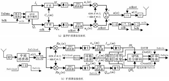
The carrier recovery module is the most critical module of the direct sequence spread spectrum receiver, as shown in Figure 2 (b). When the sampling is not synchronized with the symbol, the carrier synchronization algorithm needs to be used to achieve synchronization. Generally, an algorithm is needed to obtain carrier information from the sampled data. This article uses the Costas ring in the direct synchronization method. The structure of the loop filter is shown in Figure 3.
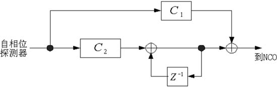
The calculation of C1 and C2 in the figure is as follows:
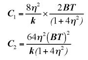
In the formula, η is the damping coefficient, generally takes a value of 0.707, B is the loop filter bandwidth, T is the symbol interval, and k is the product of the phase detector gain and the NCO gain. In the scheme of this paper, take η = 0.707, BT = 0.1, that is, the carrier recovery range is 1/10 of the symbol rate, the calculation can get C1 = 4 / 15k, C2 = 2 / 25k, adjust the value of k in the experiment to achieve The desired effect.
Modelsim simulation shows that under the 66MHz operating frequency, using a PN code with a length of 15bits, the system data rate can exceed 2Mbps. The highest spreading code rate exceeds 15Mbps (using a spreading code with a length of 15 bits). The transmitter consumes a total of 435 slices, and the receiver consumes a total of 1454 slices, accounting for about 14% of the total resources of XC3S1500.
Automatic handover design
Any mobile communication involves handover, and the wireless transmission system of train interconnection network is no exception. Due to the use of train wireless dispatch telephones, each railway station has a transmission tower for radio signals, and each railway station has a communication room. Therefore, the cell system of railway wireless communication is a circular small cell with a radius of 4 ~ 7KM as the center of each station, and its shape is shown in Figure 4.
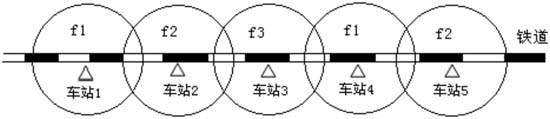
Since the transmission channel protocol provided by SBS 622M is V5 protocol, it needs to go through a protocol converter when connecting with a router. The coverage of the railway station community adopts the three-frequency system shown in Figure 4. For DS-CDMA systems, there are only three different PN sequences. This is because high-speed links are transmitted. It is important for high-speed transmission to minimize multiple access interference.
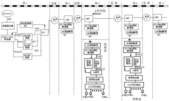
When the train is running normally in the section along the line, the IP data packet sent from station 1 is transparently transmitted through the V5 channel of SBS 622, then undergoes DS-CDMA modulation and demodulation, and returns to IP after passing through the protocol converter The data packet is sent to each PC through a broadband router and an Ethernet switch, and the IP data packet sent by the PC in the train local area network also goes through the process opposite to the above path. Since the trains run serially in one direction and there is at most one passenger train in each cell, the handover process is relatively simple and does not require power control, so the train station controls the handover. The structure of the wireless high-speed train wireless internet network system with automatic handover is shown in Figure 5.
Assuming that the train is in station 4, the PN1 sequence is used to communicate with the fixed equipment in the station. At this time, the mobile management module 1 continuously detects the input signal-to-noise ratio of PN1, and when the requirements are not met, then uses the PN2 and PN3 sequences to detect the input. If the input signal detected by the PN2 or PN3 sequence is greater than the signal-to-noise ratio of the input signal detected by PN1, after a period of delay (usually about 10 seconds to prevent interference), the mobile management module 1 A fixed channel sends a specific sequence and IP address of the network to the station equipment. At the same time, the output of the 1G buffer is blocked, but the receiving circuit works normally. This IP address sequence is sent to the mobile management module 2 of the station 1 through a fixed channel through the DS-CDMA modem of the car and station, the ONU (SBS 622), and the OLT. CISCO 7000 assigns an internal address to each station along the route as the interface number in the routing table in the router. The mobility management module 2 automatically modifies the routing table in the CISCO 7000 router based on the IP address number received by the corresponding interface, and at the same time sends a confirmation signal to the mobility management module 1 through another specific channel. After receiving this signal, the mobile management module 1 immediately controls the local DS-CDMA to switch to a new channel, and the transmission and reception are switched simultaneously. At this time, the output of the 1G buffer is also unlocked. Both parties started normal communication.
in conclusion
The wireless transmission DS-CDMA system designed and implemented for the high-speed railway interconnection network in this paper makes full use of the transmission equipment SBS 622 of the railway ground wire transmission system SDH and the direct sequence spread spectrum communication technology based on FPGA, etc., and can automatically perform handover. Since only the Internet service is opened, the indispensable equipment such as the mobile switching center MSC, the home location register HLR, and the visitor location register VLR, which were indispensable to the original mobile network, are eliminated. Features. The biggest advantage of this design scheme is that it can make full use of the original communication equipment of railway communication, give full play to the potential of the equipment, and then reduce costs and increase benefits.
Magnetoelectric Proximity Switch
The magnetic proximity switch is a kind of proximity switch. The magnetic proximity switch is one of many types in the sensor family. It is made by the use of electromagnetic working principle and advanced technology. It is a position sensor. It can transform the non-electricity or electromagnetic quantity into the desired electric signal through the change of the positional relationship between the sensor and the object, so as to achieve the purpose of control or measurement.
Motion Sensor Control Switch,Photoelectric Switch Sensors,Plug In Photoelectric Switch,Magnetoelectric Proximity Switches
Changchun Guangxing Sensing Technology Co.LTD , https://www.gx-encoder.com