Design of smart home system based on ZigBee technology
Smart home is based on residential platform, using integrated wiring technology, network communication technology, security technology, automatic control technology, audio and video technology to integrate home life related facilities, and build efficient management system for residential facilities and family schedules. Home safety, convenience, comfort, and artistry, and achieve an environmentally friendly and energy-saving living environment. Based on the latest definition of smart home, with reference to the characteristics of ZigBee technology, the system is designed based on the smart home essential system (smart home (central) control management system, home lighting control system, home security system). Joined the home wiring system, home network system, background music system and home environment control system. In the identification of smart homes, only the home system that has all the necessary systems installed completely and at least one or more optional systems can be called smart home. Therefore, the system can be called a smart home.
1 System design The system design consists of controlled devices and remote control devices in the home. Among them, the controlled devices in the home mainly have computers, control centers, monitoring nodes and home appliance controllers that can access the Internet. The remote control device is mainly composed of a remote computer and a mobile phone. The system composition is shown in Figure 1.
This article refers to the address: http://
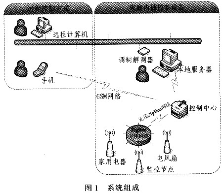
The main functions of the system are: 1) browsing of the front page of the webpage, management of background information; 2) switching control of indoor household appliances, security and lighting through two remote control modes of the Internet and mobile phones; 3) realizing user identification through the RFID module, Thereby completing the indoor security state switch, alerting the user through short message (SMS) when the thief invades; 4) completing the local control and status display of the indoor lighting and home appliances through the central control management system software; 5) using the database to complete the personal information storage And indoor equipment status storage, through the central control management system to facilitate users to query the status of indoor equipment.
2 system hardware design system hardware design includes control center, monitoring node and the choice of added home appliance controller (here, electric fan controller as an example) design.
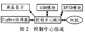
2.1 Control Center The main functions of the control center are: 1) Establishing a wireless ZigBee network, adding all monitoring nodes to the network and receiving new devices; 2) User identification, which is implemented by the user when leaving home or returning. Indoor security switch; 3) When a thief invades the room, by sending a short message to the user. Users can also control indoor security, lighting and home appliances through short messages; 4) When the system is running in a single machine, the LCD displays the current system status for the user to view; 5) Stores the status of the electrical device and sends it to the PC to implement the system connection. According to the function of the control center, its component block diagram is shown in Figure 2.
TI's CC2430 microcontroller is selected as the controller of ZigBee module. It is a high-performance, low-power 805l core microcontroller. It is also a 2.4 GHz RF device conforming to IEEE802.15.4 specification. The hardware supports carrier sense multiple access/collision detection (CSMA/CA). The working voltage of 2.0~3.6 V is beneficial to realize the system. Low power consumption. Establish a wireless star ZigBee network indoors through the ZigBee Coordinator module connected to the control center. All the monitoring nodes and the selected home appliance controllers are added to the network as terminal nodes in the network, thereby implementing wireless ZigBee network control of indoor security and home appliances.
The control center MCU uses an 8-bit microcontroller ATMegal28, which is a high-performance, low-power RISC-based microcontroller. Most instructions can be completed in one clock cycle, up to 16 MHz, and have a 128 K system. Programmable Flash, 4 Kbytes of EEPROM and 2 serial interfaces. It is connected with GSM module, RFID module, liquid crystal module, ZigBee coordinator and PC. It is the core of the whole hardware system, completes the response to the central control management system and drives each module. The GSM module uses the TC35i module. It is directly connected to the Control Center MCU via a serial UART interface. The RFID module uses the ZLG500 module, which integrates the MFRC500 type ISO14443A card reader and can read and write the RC500. EEPROM. Since the ZLG500 does not use the standard SPI interface specification, it can only be connected to the general-purpose I/O interface of the microcontroller to achieve communication. The liquid crystal module uses 1602 liquid crystal, and is connected to the general-purpose I/O interface of the control center MCU by a 4-wire interface. The ZigBee Coordinator and the Control Center MCU can realize bidirectional transmission of data between the two by using a 2-wire interface. The control center MCU is connected to the computer RS232 serial port, and the transmission data is stable, reliable, and real-time.
2.2 Monitoring node The functions of the monitoring node are: 1) detection of human body signals, sound and light alarm when thieves invade; 2) control of lighting, its control mode is divided into automatic control and manual control, automatic control is based on indoor light The strength of the power automatically turns on/off the lights. The manual control is achieved through the central control management system: 3) Send alarm information and other information to the control center, and receive control commands from the control center to complete the device control. Starting from the function of the monitoring node, the monitoring node composition is shown in Figure 3.
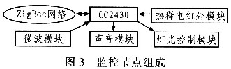
The infrared plus microwave detection mode is currently the most commonly used method for human body signal detection. Pyroelectric infrared probes use RE200B here, and amplifier parts use BISS0001. The RE200B is powered by a voltage of 3 to 10 V and has a built-in pyroelectric dual-sensitive infrared component. When the component receives infrared light, it generates a photoelectric effect at both poles of each component to accumulate charge. BISS0001 is a digital-analog hybrid ASIC composed of an operational amplifier, a voltage comparator, a state controller, a delay time timer, and a lock-up timer. It can form a passive pyroelectric infrared switch with RE200B and a small number of components. The microwave sensor uses the ANT-G100 module, the center frequency is 10 GHz, and the maximum settling time is 6 μs. Combined with pyroelectric infrared module, it can effectively reduce the target detection error rate.
The light control module is mainly composed of a photoresistor and a light control relay. Connect the photoresistor in series with a 10 kΩ adjustable resistor, ground the other end of the photoresistor, and connect the other end of the adjustable resistor to a high level. The voltage value of the two resistance connection points is obtained by the analog-to-digital converter of the single chip microcomputer, thereby determining whether the current light is turned on. The adjustable resistor can be adjusted by the user to meet the light intensity when the user sets the light just turned on. The switch of the indoor light is controlled by a relay. It only needs one input and output port.
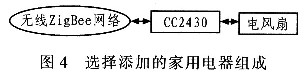
2.3 Selecting the added home appliance controller Selecting the added home appliance control mainly implements the device control according to the device function. Here, an electric fan is taken as an example. The electric fan control is realized by the control center sending the electric fan control command issued by the upper computer to the electric fan controller through the ZigBee network. Different home appliance identification codes are different. For example, the identification code of the electric fan specified in this agreement is 122, the household color TV The identification code is 123, which realizes the identification of different home appliances by the control center. For the same instruction code, the functions performed by different appliances are different. Figure 4 shows the composition of the home appliance selected for addition.
3 system software design system software design mainly includes 6 parts, respectively for remote control web design, central control management system design, control center main controller ATMegal28 program design, CC2430 coordinator program design, CC2430 monitoring node program design, CC2430 select add equipment Programming.
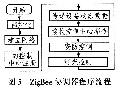
3.1 The ZigBee Coordinator's programming coordinator first completes the application layer initialization, sets the application layer state and the receive state to idle, then turns on the global interrupt and initializes the I/O port. The coordinator then begins to establish a wireless star network. In the protocol, the coordinator automatically selects the 2.4 GHz band, and the maximum number of bits transmitted per second is 62 500. The default personal area network number (PANID) is 0x1347, the maximum stack depth is 5, and the maximum single transmission is The number of bytes is 93, the baud rate of the serial port is 57 600 bit/s, and the SL0W TIMER generates an interrupt 10 times per second. After the ZigBee network is successfully established, the coordinator transmits its address to the control center MCU. Here, the control center MCU identifies the ZigBee coordinator as a member of the monitoring node, which is identified by an address of zero. The program enters the main loop. First, it is judged whether there is new data sent by the terminal node, if yes, the data is directly transmitted to the control center MCU; whether the control center MCU has an instruction to transmit, if any, the downlink command is sent to the corresponding ZigBee terminal node. Determine whether the security is open, whether there is a thief intrusion, if any, send the alarm information to the control center MCU; determine whether the light is in the automatic control state, if yes, open the analog-to-digital converter to sample, the sample value is the light is turned on or off The key is to transmit new status information to the control center MC-U if a light status change occurs. The ZigBee Coordinator program flow is shown in Figure 5.
3.2 Program Design of ZigBee Terminal Node The ZigBee terminal node refers to the wireless ZigBee node controlled by the ZigBee coordinator. In the system, it mainly monitors the node and selects the added home appliance controller. The initialization of the ZigBee terminal node also includes application layer initialization, opening interrupts and initializing I/O ports. Then try to join the ZigBee network, it should be emphasized that only the terminal nodes that are consistent with the ZigBee coordinator settings can join the network. If the ZigBee endpoint fails to join the network, it will try again every two seconds until it is successfully added to the network. After joining the network successfully, the Zi-gBee terminal node sends its registration information to the ZigBee coordinator, and then the ZigBee coordinator forwards it to the control center MCU to complete the registration of the ZigBee terminal node. If the ZigBee terminal node is a monitoring node, it implements lighting and security control. The program is similar to the ZigBee coordinator part, except that the monitoring node needs to send data to the ZigBee coordinator, and then the ZigBee coordinator transmits the data to the control center MCU. If the ZigBee terminal node is an electric fan controller, it only needs to receive the data of the upper computer without having to upload the status, so its control can be directly completed in the wireless data receiving interruption. In the wireless data reception interruption, all terminal nodes translate the received control commands into control parameters for the node itself, and do not perform any processing on the received wireless commands in the node main program.
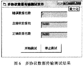
4 On-line debugging The instruction for incrementing the instruction code of the fixed device issued by the central control management system is sent to the control center MCU through the serial port of the computer, and sent to the coordinator through the two-wire interface, and then sent to the ZigBee terminal node by the coordinator. When the terminal node receives the completion, the data is sent to the PC through the serial port again, and the data received by the ZigBee terminal node is compared with the data sent by the control center on the PC. The central control management system sends 2 instructions every second. After 5 hours of testing, the test software stops the test when the total number of received data packets is 36000 packets. The multi-protocol data transmission test software test results are shown in Figure 6. The correct packet is 36 000, the number of error packets is 0, and the correct rate is 100%.
5 Conclusion Through ZigBee technology, the smart home internal networking is realized, which has the advantages of convenient remote control, flexibility of adding new equipment and reliable control performance. User identification is realized through RFTD technology to improve system security. Remote control and alarm functions are realized through the access of the GSM module.
Guangzhou Yunge Tianhong Electronic Technology Co., Ltd , http://www.e-cigaretteyfactory.com