Development of remote control flash LED test marker light
introduction
The hydrological surveying test of most hydrological stations in the lower reaches of the Yellow River uses the mechanical sextant to measure the starting point of the vertical line. It has the characteristics of quick measurement, simple use, low cost and low failure rate. It is a test equipment that cannot be replaced by other modern distance measuring instruments. The hydrological test occupies a very important position.
During the test, one marker light is installed on the two sign poles (or towers) of the flow section, and the two marker lights are used to determine whether the ship is on the section line; one baseline is installed on the baseline end marker pole. The indicator light is used to measure the angle between the line connecting the ship to the end point of the baseline and the section line, and then calculate the starting point position of the ship according to the angle and the length of the baseline.
Night traffic test, eye-catching sign light is an indispensable test facility. At present, most incandescent lamps are used as test marker lights, and 220 V AC is used to supply power to the marker lamps. There are several problems in this type of signage: 1) special transmission lines need to be set up, and the phenomenon of stealing power lines in remote villages occurs, which not only causes certain economic losses, but also affects the normal hydrological test. Most hydrological stations are stationed in rural areas, electricity supply is not as good as cities, sometimes power outages will affect the test; 2) ordinary incandescent lamps are used as sign lights, which are indistinguishable from other light sources and are easily confused with other light sources. It is prone to target errors, resulting in wrong starting point data; 3) incandescent lamp has a short life span, and it is often necessary to climb a sign pole of more than ten meters to replace the bulb, which brings unnecessary trouble to the tester. In order to solve these problems and improve the nighttime measurement capability, according to the actual application and requirements of the marker lamp, a new remote-controlled flash LED test marker lamp was developed.
1 Remote Flash LED Test Mark Light Principle
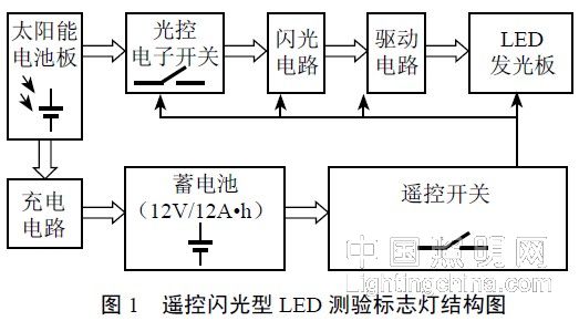
According to the design requirements, the remote control flash LED test sign lamp is composed of 8 parts including solar panel, charging circuit, battery, remote control switch, light control electronic switch, flash circuit, drive circuit and LED illuminating board. The specific structure is shown in the figure. 1 is shown. The principle of the remote flash LED test light is shown in Figure 2.
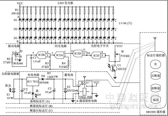
The function of each component in Figure 2 is as follows: D4 is a protection diode; IC1 is a linear regulator integrated circuit, model 7812, output stable 12 V DC voltage; D5 is a boost diode, due to its role, IC1 output voltage The boost is 13.8 V; C2 and C3 are filter capacitors; W is the light control adjustment potentiometer, and the time when the marker lamp is lit (or extinguished) according to the natural brightness; U1 is a phototransistor for detecting outdoor brightness; IC2 is for non-existence The gate circuit consists of 4 independent units, namely IC2A, IC2B, IC2C, IC2D; V1 is the drive tube, and the drive capability is strong; D1, D2, D3 are LED illuminators; R is the resistor.