Use 555 to form IS flasher circuit
555 constitutes the IS flasher circuit diagram as shown below, the circuit consists of a transformer, a diode resistor, a 555 integrated circuit and a 7410 integrated circuit, the circuit frequency of which is 60 Hz. A1 is a 7410 decimal counting circuit. After a very frequent frequency, the output frequency is 3 Hz. The 555 connected to the monostable circuit adjusts the oscillation frequency to 1/3 of the source by RP, so the light-emitting diode (diode, also called a crystal diode, referred to as a diode; it only transmits current in one direction of the electronic part. It is a kind A device having two terminals joined by one part number has a property of causing a current to flow or not to flow according to a direction of an applied voltage) to flash once every 1 s.
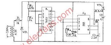
555 constitutes the IS flasher circuit diagram
A concave grating has the advantage of setting up a spectroscopic system without any imaging optics like concave mirrors. For this reason, the concave grating is used in a wide range of applications, such as analytical instruments, optical communications, biotechnology, and medical instruments. Spectroscopes incorporating concave gratings are classified roughly into two categories: polychromators or monochromators. holographic concave gratings are recorded on spherical substrates, with equidistant and parallel grooves.
Holographic Concave Grating,Angle Of Diffraction Grating,Holographic Diffraction Grating,Ruled Grating
Changchun Realpoo Photoelectric Co., Ltd. , https://www.optics-realpoo.com