Low-power high-voltage power supply circuit diagram based on BUCK voltage regulation
Overview:
This paper designs an adjustable low-power high-voltage power supply. The main circuit topology includes Buck module, inverter circuit, high-frequency transformer and voltage doubler circuit. The input AC power is converted to DC through the rectification and filtering circuit, and the voltage is stabilized by the BUCK pre-regulation circuit, and then the DC voltage is changed into an AC voltage through the half-bridge inverter circuit, and then the voltage is raised by a voltage multiplying circuit, and finally rectified. The filtered output is stable at high voltage.
The main contents of the research include analysis design of BUCK circuit, analysis design of half-bridge inverter circuit, design of voltage doubler circuit, design of control circuit, and simulation and parameter optimization of corresponding parts by PSPICE software.
The main performance achieved in this study is: the given input voltage is 220V AC, the output voltage is required to be widely adjustable in the range of 0~15KV, the power is 15W, and the output ripple is less than 1%.
0 Introduction High-voltage power supply generally refers to a power supply with an output voltage of more than five kilovolts. Generally, the output voltage of a high-voltage power supply can reach tens of thousands of volts, or even hundreds of thousands of volts or more. High-voltage power supplies are widely used in materials modification, metal smelting, environmental protection, high-power laser and microwave applications. The traditional high-voltage power supply adopts the power frequency power supply and the LC resonance mode. Although the circuit is simple, its volume and weight are large, the low-frequency working state, ripple and stability are not satisfactory. With the development of power electronics, the high-frequency high-voltage power supply becomes The trend of development.
With the emergence of new electronic components, new electromagnetic materials, new power conversion technology, new control theory and new professional software, and constantly applied to switching power supplies, the performance of switching power supplies continues to improve, characteristics Constantly updated, new features such as high frequency, high efficiency, high power density, and high reliability have emerged.
A revolution occurred in the history of the world's power supply in the 1970s, that is, the 20Hz switching frequency combined with pulse width modulation (PWM) technology in the power field. So far, the frequency of the power supply has reached hundreds of Hz, and advanced quasi-resonant technology can even reach the mega Hz level. Increasing the oscillator output frequency can reduce the basic performance requirements and structure volume of high-voltage transformers, reactors, smoothing capacitors, high-voltage capacitors and other electronic devices, thereby reducing the volume of the high-voltage power supply. The high frequency makes the volume of the high voltage power supply greatly reduced, light and portable, and the practicality and ease of use are obviously improved.
In recent years, with the development of electronic power technology, new-generation power devices, such as MOSFETs, IGBTs, etc., the high-frequency inverter technology has gradually matured, and high-voltage switching DC power supplies have emerged. Compared with linear power supplies, high-frequency switching power supplies The outstanding features are: high efficiency, small size, light weight, fast response, low energy storage, short design and manufacturing cycle. Due to its superior characteristics, it has gradually replaced the traditional high-voltage linear DC power supply.
With the gradual application of high technology, new technical problems have also emerged, mainly in the high frequency to improve power performance and reduce the volume and ripple factor of the transformer. However, due to the high frequency and high voltage transformers coexisting with high frequency and high voltage, new technical difficulties have emerged:
1 The high-frequency high-voltage transformer is reduced in volume, the frequency is increased, the distributed capacitance is reduced, and the insulation problem is abnormal;
The 2 large voltage change ratios make the nonlinearity of the transformer serious, and the leakage inductance and distributed capacitance increase, so that it must be isolated from the inverter switch. Otherwise, the spike will affect the normal operation of the inverter circuit, and even break down the power device. ;
3 high frequency leads to enhanced skin effect of the transformer, which reduces the efficiency of the transformer.
In view of the above situation, how to design a high-frequency high-voltage transformer is a difficult and hot issue in current research.
The main contents of the research include analysis design of BUCK circuit, analysis design of half-bridge inverter circuit, design of voltage doubler circuit, and system simulation research. The circuit comprises an input rectification filter circuit, a BUCK pre-regulation circuit, a half-bridge inverter circuit, a voltage doubler circuit and an output rectification filter circuit. The input AC power is converted to DC through the rectification and filtering circuit, the voltage is stabilized by the BUCK pre-regulation circuit, and the DC voltage is changed to the AC voltage through the half-bridge inverter circuit, and then the voltage is raised by a voltage doubler circuit, and finally the rectifier is rectified. The filtered output is stable at high voltage.
1 main circuit design
1) Topology of the main circuit (Figure 1) 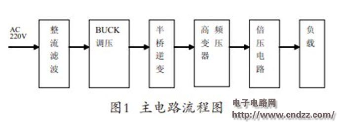
Here we mainly introduce a low-power high-voltage power supply based on BUCK voltage regulation. The power supply enables zero-current soft switching (ZCS) and easy adjustment of the output voltage because of the parasitic parameters of the high-frequency transformer, thereby avoiding spike voltages and currents. Another feature of the power supply is that the voltage doubler circuit is used instead of the traditional diode rectifier circuit, which reduces the ratio and parasitic parameters of the high frequency transformer; especially the control of the main circuit adopts the joint strategy of the Buck circuit and the inverter circuit. That is to say, Buck can be used to adjust the voltage very conveniently and flexibly; the inverter circuit with fixed frequency and fixed width can realize the resonant soft switch by using the parasitic parameters of the high frequency transformer.
In addition, since the power supply does not need to adjust the voltage of the inverter circuit to adjust the voltage, the magnetic properties of the high-frequency transformer can be fully utilized; and since the control circuit adopts a DSP-based real-time digital PI mediator, the circuit is realized. Steady state and transient characteristics.
(Please read the PDF for details)
M8 series connectors provides a wide range of metric for small Sensors and actuators.The ingress protection is available and rated to IP 67, these connectors are ideally suited for industrial control networks where small sensors are required. Connectors are either factory TPU over-molded or panel receptacles supplied with sold-cup for wire connecting or with PCB panel solder contacts. Field attachable / mountable Connector is also available for your choice.
M8 Connector,M8 Male Angled Connector,Wireless M8 Connector,3 Pin Female Connector,M8 4 pin connector
Kunshan SVL Electric Co.,Ltd , https://www.svlelectric.com