Design of High Precision Intelligent AC/DC Voltage Data Acquisition System
Overview:
Voltage is one of the most basic measurement elements in electronic and power systems. Fast and accurate voltage acquisition has always been one of the important contents of data acquisition and electronic measurement instruments. The traditional pointer voltmeter has the defects of low precision, close visual distance and single function, which is not suitable for the development of high-speed informationization. At present, the digital voltmeter widely used on the market has a low degree of intelligence. When measuring voltage, it is necessary to manually switch the range. If the range selection is not correct, the measurement accuracy will drop, and even the extreme situation of the voltmeter will be burned out. Digital voltmeters generally use complex circuits such as DSP, FPGA or CPLD, and the hardware and software implementation costs are high. To this end, the author designed and developed a smart AC DC voltage data acquisition system with single-chip microcomputer as the main control body, which has the advantages of small size, high precision, simple structure, convenient use and reading, high cost performance and wide adaptability. Make up for the shortcomings and drawbacks of the above various voltmeter systems.
1 System overall scheme The voltage data acquisition system is mainly composed of five parts: voltage attenuator, range conversion and amplification circuit, AC/DC conversion circuit, A/D conversion circuit, main control single-chip STC89C52 and LCD display circuit. As shown in Figure 1. The voltage attenuator and the amplifier convert the analog signal voltage value to be tested into the input voltage range of the AC/DC converter, and the DC voltage is attenuated and amplified without AC/DC conversion; the range conversion circuit is based on the input to the A/D converter. The size of the analog DC voltage is determined by the MCU, and the control relay adjusts the attenuation amplifier circuit accordingly to ensure that the optimal range is selected. The A/D conversion is initiated by the MCU, and the collected data is digitally filtered and scaled in the software. After processing such as transformation and system error calibration, the measured value and voltage type are displayed on the LCD according to the voltage type flag. 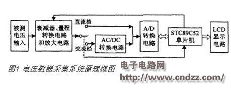
ULN2003 chip internal diode negative common terminal COM is connected to the load power supply +5 V, which acts as a reverse freewheeling action for each relay coil. The purpose of adding the inverter 74HC04 is to prevent the input high voltage from directly entering the low-level weak current system without causing the partial voltage to cause the circuit to burn out when the single-chip microcomputer system is powered on or reset. The op amp U3 is connected in the form of a voltage follower, which functions as a channel before and after isolation, and reduces the output impedance and improves the load capacity. Among them, R6 and R7 are current limiting resistors to prevent excessive current caused by the range switching to each range; D1 and D2 are bidirectional limiting diodes, which provide overvoltage protection. The op amp A4 and the resistors R8, R9, and R10 are connected to the same analog circuit, and the signal attenuated in the range of 0 to 200 mV is amplified by 10 times and sent to the following AC/DC converter AD637J (nominal full scale is 2V) for AC/ DC conversion f DC does not need to be converted).
(Please read the PDF for details)
Customers looking to customize electronic products for their business applications, we are here to understand your needs and help you with electronic hardware design. We have engineering resources to assist your business with electronic work. For any level of electronics problem you are facing right now, we have experts who can solve your problem.
PCB Prototype,PCB Prototype Design,PCB Gerber Design,PCBA Program Development,PCB Schematic
Huizhou Liandajin Electronic Co., Ltd , https://www.ldjpcb.com