Design and analysis of voltage doubler rectifier circuit, analysis of multi-voltage circuit principle, classic demonstration of bridge rectifier circuit
In order to obtain the value of the output voltage of the voltage doubler rectifier circuit, it is first necessary to clarify under what conditions the diode in the circuit is turned on and under what conditions. To simplify the analysis, the load is open and the circuit has entered a steady state, then the voltage on each capacitor is analyzed one by one, and finally the output voltage is obtained.
Taking Figure 1 as an example, let B point be ground and the effective voltage of the transformer secondary side be U2.
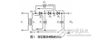
Voltage on C1: When u2 is half a week, that is, point A is "+", point B is "-", as indicated by the solid line in the figure, current is charged from A through D1 to C1, and the voltage on C1 is stable when  , up and down. Whether D2 is turned on during the positive half cycle of u2 depends on the voltage on C2.
Voltage on C2: It is impossible to charge C2 through D2 when u2 is half a week. In fact, when u2 is negative for half a week, that is, point A is "-", point B is "+", the voltage on u2 and C1 is superimposed through D2 to C2. Charging, as shown by the dotted line in the figure, so when the steady state is reached, the voltage on C2 can reach  The polarity is right and left negative.
Voltage on C3: When u2 is half a week, if C2 has entered steady state, it will be superimposed with u2 to charge C3 through D3. As shown by the dotted line in the figure, the voltage on C3 can reach  The polarity is positive and negative. Therefore, the output voltage
  It can be seen that this is a triple voltage circuit.
It must be pointed out that the charging transition process of the three capacitors occurs simultaneously, and after entering the steady state, all three diodes are turned off. After carrying the load resistor and entering the steady state, there are charging and discharging processes of the respective capacitors in each cycle of u2, but the proportional relationship of the average voltages on the respective capacitors is basically unchanged.
How is the multi-voltage rectifier circuit implemented?
The Cochcroft & Walton circuit shown below is a typical multi-voltage rectifier circuit.
Multi-voltage rectifier circuitWhen several half-wave voltage doubler rectifier circuits composed of diodes and capacitors are connected in series in several stages, the AC voltage is charged and discharged in series and parallel to the capacitors C1 to Cn through the diodes D1 to Dn every half cycle. The AC input voltage can be used to obtain several times the DC output voltage of a single-stage half-wave voltage doubler rectifier circuit.
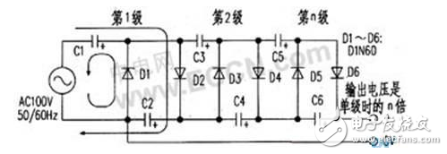
The working process is: first, during the negative half cycle of the alternating current, the alternating current source charges C1 through D1, then the alternating current source and the voltage on C1 are added in the positive half cycle, and the capacitor C2 is charged through D2, and the charged voltage is the charging voltage of the capacitor C1. Twice. Next, in the negative half cycle, in addition to the power supply charging the capacitor C1 via D1, the AC power supply is superimposed with the voltage on C2 via D3 to charge C3, C1, and the charging voltage on C3 is twice that on C1. During the positive half cycle, the AC power supply is superimposed with the voltage on C1. In addition to charging capacitor C2 via D2, it also superimposes the voltage on C1 and C3 via D4 to charge capacitors C4 and C2. The voltage charged on C4 is capacitor C1. Double the voltage. By analogy, it can be seen that the output DC voltage is related to the number of stages of the half-wave voltage doubler rectifier circuit. The figure is connected in series with a three-stage half-wave voltage doubler rectifier circuit. The charging voltages on C2, C4 and C6 are twice the charging voltage on C1. After three capacitors are connected in series, the charging voltage is six times the charging voltage on C1.
Bridge rectifier classic circuit:The basic circuit of bridge rectification, for the unmanned students, is the first to face this kind of circuit; it will be overly abstract and difficult to understand: so I designed this "bridge rectification" demonstration circuit (see below) Figure). j It utilizes the unidirectional conduction characteristics of the LED to visually represent the current flow.
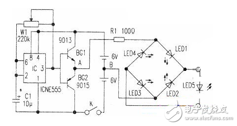
The IC is connected to a self-excited multi-resonant circuit whose oscillation frequency is controlled by C1 and W4. The oscillating signal output from the IC3 pin controls BG1 and BG2 to be turned on in turn, so that the potential at point A becomes high and low alternating current with respect to point B. When the lC3 pin outputs a low level, BG2 is turned on, and BG1 is turned off, so that point A is low level, point B is high level, and current flows through B→LED2→LED5→LED4→A. At this time, LED2, LED5, and LED4 all emit light. When the IC3 pin outputs a high potential, BG1 is turned on, BG2 is turned off, point A is high, and point B is low. At this time, the current flows through A→LEDI→LED5→LED3→B, and LED1, LED5 and LED3 all emit light, so that the whole circuit simulates the bridge rectification process. In the circuit, LED5 is used to demonstrate the positive and negative polarity of the output of the bridge rectifier circuit.
Component selection and productionThe IC selects the time base circuit NE555 or HA17555. C1 and W1 can be selected according to the actual situation to meet different needs. Five LEDs can be selected for high brightness, but LED 5 is preferably different from the other four LFD colors. The battery can be used with two 6V stacked batteries. The whole circuit can be mounted on a large plywood. Five LEDs are mounted on the front side of the board, and the bridge rectification circuit is drawn at the corresponding position. It is worth noting that the value of C1 should be such that the LED has obvious resolution when it is turned on and off in turn. Adjusting Wl can change the oscillation frequency, that is, the frequency of the alternating current is equivalently changed. If a voltmeter is connected to two points A and B, in the static state, the pointer is pointed at the middle reticle position. In this way, as the BGI and BG2 turn on and the pointer can swing left and right, it can be more intuitively demonstrated that "the direction of the alternating current is constantly changing."
Air fryer,High Quality Air fryer,Air fryer Details, CN
Ningbo ATAP Electric Appliance Co.,Ltd , https://www.atap-airfryer.com