How to calculate the special baud rate of CAN
The CAN bus uses asynchronous serial communication, that is, there is no separate clock line to ensure the clock consistency between the transceivers. Each transceiver divides the level on the bus according to the preset baud rate. . Therefore, the baud rate setting is very important for the stable communication of the CAN bus.
In the CAN bus, we can achieve different baud rate communication by controlling the bit timing registers in the CAN node. In the CAN protocol, a bit time is divided into a sync segment, a propagation segment, a phase buffer segment 1 and a phase buffer segment 2. The length of each segment can be expressed in terms of an integer basic time unit, which is obtained by dividing the system's clock oscillator.
The sync segment is located at the beginning of a bit. CAN-bus specifies that the edge of the transition is a sync signal. However, there is a network propagation delay between the transmit node transmitting a bit and the receiving node receiving the bit, and the propagation segment is to compensate for this propagation. Delay, since the sampling point position is between the phase buffer segment 1 and the phase buffer segment 2, by setting the values ​​of the phase buffer segment 1 and the phase buffer segment 2, the sampling point position can be adjusted to ensure that each bit sampling point is consistent. The length adjustment range of the buffer segment is determined by the sync jump width (SJW).
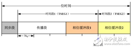
Figure 1 CAN bit time structure diagram
After a brief understanding of the segmentation of the CAN bus bit time, let's look at how the baud rate of a node is set. Figure 2 shows the CAN bit time characteristic register (CAN_BTR) of an ARM core.

Figure 2 An ARM core bit time characteristic register structure
SILM (silent mode) and LBKM (loopback mode) are used for debugging;
SJW: synchronous jump width;
TS2/TS1: allocation of two time periods in bit time;
BRP: baud rate divider, which defines the length of the basic time unit;
For example, a famous car manufacturer's CAN communication standard stipulates that when the communication rate is 125 kbps, a single sampling should be used, and the sampling point position is set between 70% and 77%. The values ​​of the bit timing parameters can be seen in Table 1 and Table 2.
Table 1 LS_CAN communication rate and sampling point parameters
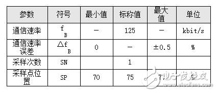
Table 2 LS_CAN optional time share and synchronous jump bandwidth

Sampling point: The sampling point can't be too far forward or too late. Otherwise, if it is just in the rising edge or falling edge of a bit, it will cause recognition error. Therefore, according to the CIA105 specification, the sampling point is suitable at around 87.5%. However, in general, we can choose between 75% and 85% according to the actual situation;
Synchronous jump width (SJW): The value of SJW directly affects the adjustable range of the phase buffer segment during resynchronization. The value of SJW can be selected between 1 and 4. We choose 3 and 4 to make the bus wider. Baud rate tolerance;
Number of sampling: divided into single sampling and three sampling. Although the sampling is designed to filter out the burrs on the bus at the beginning of the design, the use of three samplings often affects the SJW jump. Therefore, in practical applications, we usually use single sampling. .
After understanding the principle of setting the baud rate, we use ZLG's baud rate calculation software to calculate the setting parameters of the 25kbps baud rate. The calculation result is shown in Figure 3.
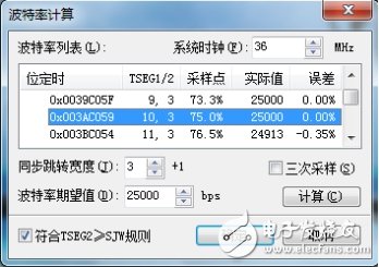
Figure 3 25kbps baud rate calculation parameters
According to the above mentioned principle, we select a set of parameters with a sampling point of 75%, SJW of 4, and a time share of 14, using ZLG's CAN card for verification.
· Automatic baud rate recognition: Using CANScope to automatically detect the baud rate function, the baud rate of the CAN card is recognized, and the recognition result is 25kbps;

Figure 4 automatically detects the baud rate
· Sampling point test: Using CANScope to test the sampling point of the CAN card at the current baud rate, the test result is 75%;

Figure 5 sampling point test
· Bit width tolerance test: Using CANScope to test the bit width tolerance of the CAN card at the current baud rate, test its tolerance to the baud rate, the test result is 24kbps~26kbps, and the tolerance is better;
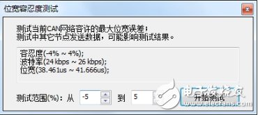
Figure 6 bit width tolerance test
· Bit time test: Use CANScope's eye diagram function to test the bit time of the CAN card at the current baud rate. The bit time is 40us, which matches the bit time of the 25kbps baud rate.
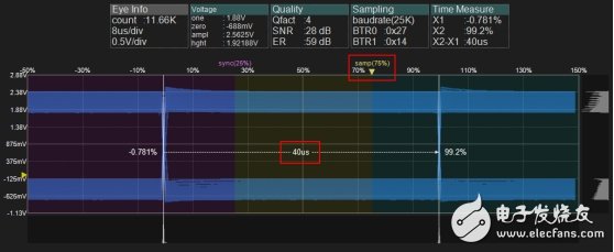
Figure 7 Eye test position time
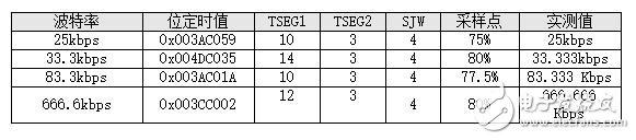
By verifying the baud rate register setting parameters calculated by the baud rate calculator, it is found that the test results are consistent with our expected results, so when using the special baud rate, we can quickly calculate by using the baud rate calculator. The parameter value of the bit timing register. Below we give some parameters for the special baud rate that can be referenced:
Fiber Cable Types,Fiber Optic Cable Types,Fiber Optic Ethernet Cable,Single Mode Fiber Optic Cable
Zhejiang Wanma Tianyi Communication Wire & Cable Co., Ltd. , https://www.zjwmty.com