Geomembrane burst strength tester installation method and structure diagram - Database & Sql Blog Articles
Geomembrane bursting strength tester installation method and structure diagram
Geomembrane burst strength tester installation and use method:
1
, pressure setting: press the set button "back" after power on
Press the shift key"
>
â€
Press the adjustment button again"
+
"with"
--
†Adjust the value again, adjust it, press the set button “Back†to save it. After adjusting the lower limit value, press the set button to exit.
2
The method of setting the peak value of the pressure (the peak value is kept at the maximum pressure when the specimen is broken): long press and save
3
The second enters the setting state, and the time window is displayed as
B
When set to
0
, representing the pressure peak retention,
It can be set to any time unit, minute, and the lower limit rises to
0.1MPa
3
, time clear: re-do the experiment, keep pressing "
--
"The key is not released, the time value is displayed first.
10
After the second time is available from
0
Minutes start, "!" can't be mistakenly pressed when working.
4
Time review: press
"-"
The key pressure is displayed in hours, the upper limit is minutes, and the lower limit is seconds.
30
Return to the pressure display after a second,
5
, time setting, long press to deposit into the building
3
The second enters the setting state, and the time window is displayed as
T
The pressure increment time can be set. The unit is minutes.
3
, Zero adjustment: If there is no pressure after starting, if it does not return to zero, press once to set zero. Do not press the clear button when there is pressure, and then zero after releasing the pressure.
.
4
, open the water injection cover, add pure water
.
Until the tank is full
.
Start the pressurization and open the pressure regulating valve to allow water to flow into the high pressure chamber chassis to just overflow.
5
Place the sample without wrinkles on the rubber ring in the water collector, overflow excess water to ensure no air bubbles in the clamp; cover the upper pressure plate and evenly clamp the sample.
6
To
10
The highest value of the measured pressure-resistant pressure values ​​was taken as the hydrostatic pressure resistance value of the sample.
7
The test results are calculated according to relevant standards.
Schematic diagram of geomembrane bursting strength tester
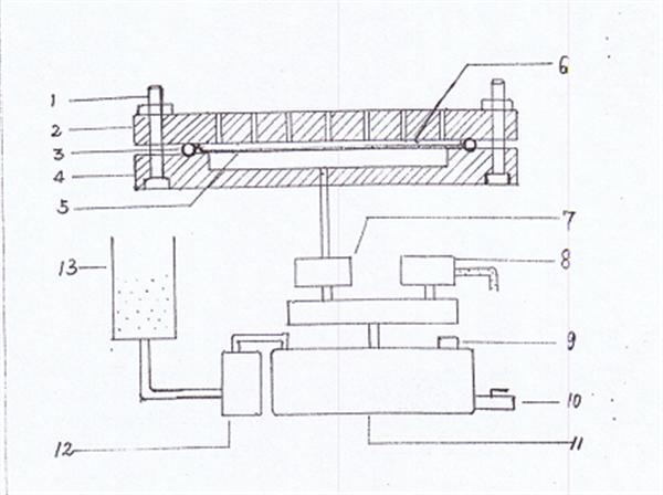
1.
Fastening screw
2.
Upper platen
3.
Sealing ring
4.
High pressure tank chassis
5.
Steel mesh
6.
Specimen
7.
Pressurized inlet valve
8.
High pressure tank drain valve
9.
Pressure Sensor
10.
System drain valve
11.
pressure tank
12.
High-pressure pump
13.
Water bucket

Incremental Encoder,Linear Scale Encoder,Dual Concentric Rotary Encoder,Dc Servo Motor Encoder
Yuheng Optics Co., Ltd.(Changchun) , https://www.yhenoptics.com