System design based on FPGA and high speed A/D converter chip ADC08D1500
Abstract: In order to simultaneously calculate the correlation of four Stokes vector parameters and invert the sea surface wind field, a new digital correlator design method is proposed. Combined with the application of high-speed digital correlators in digital polarimeter, high-speed data sampling and related processing systems are introduced. Four high-speed A/D converters (ADC08D1500) are used to simultaneously sample four signals. The sampling results are processed by Xilinx's next-generation field-programmable gate array (FPGA)-Virtex5 chip. The relevant results are uploaded to the computer through the serial port. The interface circuit and timing control design of each part of the system. The system can calculate the correlation of up to 1.5GHz sampling rate of four signals.
0 PrefaceThe study of wind surface on the ocean surface is of great significance in meteorology, oceanography and climatology. The new technical feature of the full-polarization radiometer is that the multi-path correlation technique is used to correlate the horizontal and vertical polarization signals to generate the parameters needed to invert the sea surface wind field model. The modified Stokes vector can be used to describe the second-order statistical properties of the radiation field in space. The elements in the modified Stokes vector are in light temperature K as shown in the following equation.
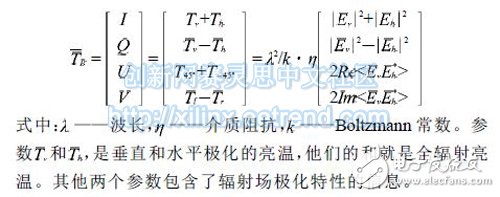
Four Stokes parameters can be obtained by correlating the two signals of vertical and horizontal polarization. Currently used polarized radiometers mostly use analog correlators. However, with the increasing requirements for wind field measurement accuracy, analog multiplying devices have not met the requirements. A digitally polarized radiometer refers to the use of a digital correlator to achieve autocorrelation and cross-correlation processing of two polarized channels. Compared with analog correlators, digital correlators are characterized by the ability to use resource-changing speeds to achieve full parallel wideband digital correlation processing using VLSI technology. The digital correlator samples the analog signal and then quantizes the data for correlation operations. According to Nyquist's sampling law, the sampling frequency must be greater than or equal to twice the bandwidth of the sampled signal to avoid loss of information. This makes the sampling circuit operate at a very high frequency, which places high demands on the accuracy and reliability of the circuit. This paper introduces a high frequency and high reliability signal sampling and correlation processing system. The high-speed ADC in this system uses NS's ADC08D1500, which has the advantages of high precision and low power consumption, and can work at the highest sampling rate of 1.5GHz. The FPGA chip has the characteristics of small size, high integration, and low power consumption. Data reception and related calculations are done with FPGA as the core.
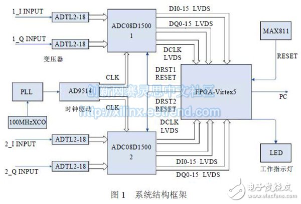
1 digital correlator designIn the signal acquisition module, two ADC08D1500s simultaneously sample four signals. The ADC output data is in LVDS mode with a single ADC bit width of 32 bits and parallel output. The Xilinx FPGA-Virtex5 is used to receive and correlate the output data of two ADCs. The FPGA also implements reset control of the two ADCs, which can trigger the simultaneous operation of the two ADCs. In this scheme, the high-speed clock driver AD9514 is used to drive the sampling clock to ensure the phase consistency of the sampling clock signals reaching the two ADCs. The relevant results of the FPGA calculation are uploaded to the PC through the serial port. The system block diagram is shown in Figure 1.
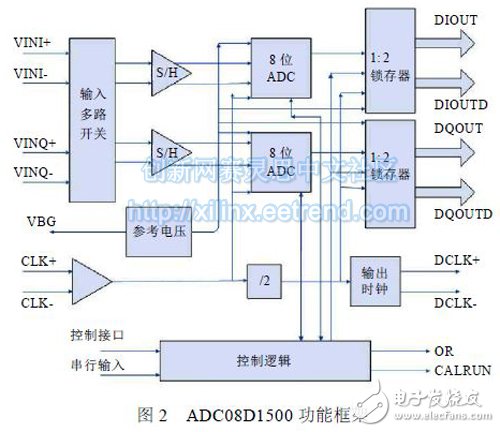
The ADC uses two ADC08D1500 chips. National Semiconductor's high-speed ADC-ADC08D1500 [3] is a high-performance analog-to-digital converter chip with a typical power consumption of 1.9W. In this digital correlator, each channel has a sampling rate of 1.5 GHz, 8 bit resolution, and a full power bandwidth of 1.7 GHz. The input peak-to-peak value is 870Mv through the pin configuration setting. The ADC is automatically calibrated after 231 sample clock cycles.
DCLK is sent to an external device to latch the data. DCLK operates in DDR transfer mode. The ADC internally performs 1:2demux, and the output clock is divided by two of the sampling clock. This approach reduces the clock rate into the FPGA to 1/4 of the sampling frequency, making it convenient for high-speed correlation calculations. The OR pin is high indicating that the input is out of range. Connect the OR to the FPGA and drive the external LEDs of the FPGA. Figure 2 shows the functional block diagram of the ADC.
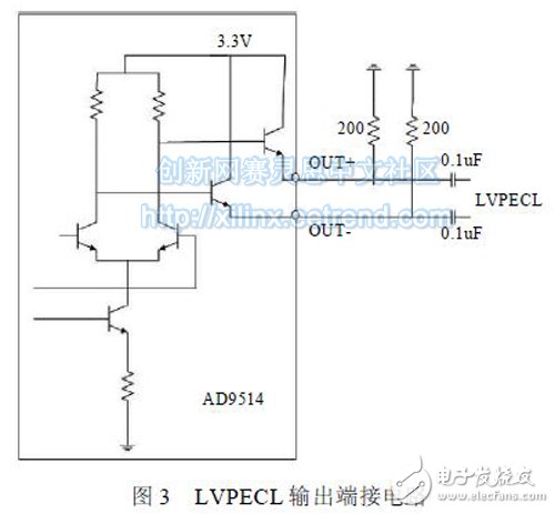
The ADC08D1500 requires a differential clock input. The sampling clocks of the two ADCs need to be strictly synchronized to achieve their amplitude and phase consistency requirements. In the design, the clock drives the AD9514 to separate two in-phase differential clocks. ADI's high-performance clock driver chip AD9514 input level is LVPECL, LVDS, the output signal is LVPECL, LVDS, CMOS level. Two LVPECL level outputs are ac-coupled to two ADCs with a maximum output of 1.6 GHz, as shown in Figure 3 for its LVPECL output circuit.
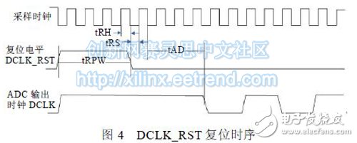
Synchronous reset of the two ADCs is the primary method to ensure that the ADCs work synchronously. DCLK_RST is the reset pin of the ADC. A positive pulse can reset and synchronize the DCLK output of multiple ADCs. The reset signal must be valid for more than 4 sample clock cycles. As shown in Figure 4, trpw is at least 4 sample clock cycles. Simultaneous reset of the two ADCs is implemented by the FPGA controlling the DCLK_RST pin. The recovery time Tad is 3.5ns.
Uni Directional Mic,Uni Directional Microphone,Uni Directional Dynamic Microphone,Uni Directional Condenser Microphone
NINGBO SANCO ELECTRONICS CO., LTD. , https://www.sancobuzzer.com