MAX1555: New Li-Ion Battery Charger
The rapid development of portable communication devices and computers has led to an increase in the number of lithium-ion batteries, which has led to continuous improvement of the chargers associated with them, and new types of lithium-ion battery chargers have emerged one after another. The new charger can be summarized as follows:
1. The charger lC has a small size and few external components. The entire charger circuit occupies a small printed board and can be loaded into an electronic product (there is no separate charger). It can be charged by the USB port to make it more usable. For convenience.
2, plug-in power supply (AC / DC adapter) or USB port can be used as charging power (and automatic switching function), making it easy and flexible to carry and use.
3, perfect charging process: when the battery is low voltage or over-discharge (less than 2.5V), pre-charging with a small current; fast constant current charging; constant voltage full, battery charging voltage can meet the accuracy of ± 1%.
4. The charging core is regulated by the charging core temperature during the charging process, which simplifies the circuit board design and ensures the safety of the IC.
This article describes the MAX1555 single-cell Li-Ion battery charger. The main features of the charger: the plug-in power supply or USB socket can provide charging power (the voltage range of the plug-in power supply is 3.7V ~ 7V, the USB power supply voltage range is 3.7V ~ 6V), the typical supply voltage is 5V; When the power supply is used, the charging power supply is typically 280mA. When the USB socket is used, the charging current is 100mA. The peripheral components are only 3 1μF SMD multilayer ceramic capacitors and 1 SMD lkkΩ pull-up resistor. The board surface is too small, it may be loaded into the product: there is charging status indication; there is overheat limit inside, once the overheat limit temperature is reached, the charging current is automatically reduced to ensure charging safety; 5 pin small size SOT-23-5 package; Operating temperature -40 ° C ~ +85 ° C.
Pin arrangement and function
The MAX1555 pins are arranged as shown in the figure below, and the functions of each pin are shown in the table.
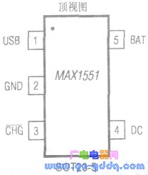
| Pin | symbol | Features |
| 1 | USB | Input powered by a USB outlet. USB needs to provide 10000mA charging current. Connect a 1μF decoupling capacitor between this terminal and GND. |
| 2 | GND | Ground |
| 3 | CHG | Charger status signal output. Internal open drain output. An external 100kΩ pull-up resistor is required. This terminal outputs a low level during charging. At the end of charging, this terminal is high impedance. In addition, when both supply voltages are lower than the required minimum voltage, this terminal is high impedance. |
| 4 | DC | Plug-in power supply input. The power supply needs to supply 280mA of charging current. This terminates a 1μF ceramic capacitor to ground. |
| 5 | BAT | Connect the rechargeable battery terminal (positive), which terminates a 1pF decoupling ceramic capacitor to ground. |
Typical application circuit and charging process
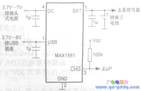
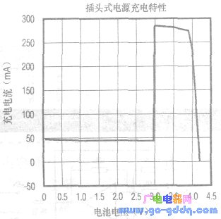
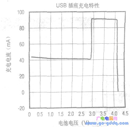
The typical application circuit for the MAX1555 is shown above. The charging process of the charger is divided into three stages: pre-charging when the battery voltage is lower than 3V, fast charging when it is 3V or close to 3V, and when it is close to 4V, constant voltage charging, the current is reduced, and charging is completed when charging to 4.2V. The charging process of the plug-in power supply is shown in the figure below. The charging process when charging the USB socket is as shown below.
Regardless of the power supply, the battery is fully charged at 4.2V ± 0.059V. After the charging process or charging is completed, the maximum leakage current of the battery is 5 μA when the power is removed. In order to prevent the polarity of the power supply from being reversed when the power supply is plugged, a 1N4001 (anti-power polarity reversed) protection diode (not shown in Figure 2) can be connected in series before the DC terminal (4 pins). In addition, when charging with a USB socket, if a plug-in power supply is inserted at this time, the internal can be automatically switched to be charged by the plug-type power supply.
ZGAR bar 3000 Puffs
ZGAR electronic cigarette uses high-tech R&D, food grade disposable pod device and high-quality raw material. All package designs are Original IP. Our designer team is from Hong Kong. We have very high requirements for product quality, flavors taste and packaging design. The E-liquid is imported, materials are food grade, and assembly plant is medical-grade dust-free workshops.
Our products include disposable e-cigarettes, rechargeable e-cigarettes, rechargreable disposable vape pen, and various of flavors of cigarette cartridges. From 600puffs to 5000puffs, ZGAR bar Disposable offer high-tech R&D, E-cigarette improves battery capacity, We offer various of flavors and support customization. And printing designs can be customized. We have our own professional team and competitive quotations for any OEM or ODM works.
We supply OEM rechargeable disposable vape pen,OEM disposable electronic cigarette,ODM disposable vape pen,ODM disposable electronic cigarette,OEM/ODM vape pen e-cigarette,OEM/ODM atomizer device.

Disposable Vape, bar 3000puffs, ZGAR bar disposable, Disposable E-cigarette, OEM/ODM disposable vape pen atomizer Device E-cig, ZGAR 25 Vape
ZGAR INTERNATIONAL TRADING CO., LTD. , https://www.zgarecigarette.com