Power supply in parallel: power supply simplified design
System designers want to consider the possibility of using DC power supplies in parallel for many reasons. Some of them are related to bill of materials and logistics issues, others are focused on meeting system current, performance or reliability goals.
In terms of non-design, the ability to connect parallel power supplies also allows a single power supply to be used alone or in combination across a wide range of product lines. This simplifies procurement, increases the amount of a single power supply, and simplifies inventory management.
Of course, the technical reasons for considering parallel power supplies are more complicated. First, perhaps because of the inability to obtain components with lower power consumption, or the market has added new selling points and new features, the product may actually require more current than the budget, and the use of parallel power supplies may be an "insurance" form. Secondly, the parallel power supply can support N+1 or even N+2 redundancy to prevent single point of failure or to implement hot swapping of the faulty power supply without affecting the system. Third, it allows the use of proven power supplies that are well known for their features, features, and form factors, thereby reducing design introduction risk and uncertainty. Finally, if a high power unit dissipates too much heat in a highly confined area, it can achieve "thermal diffusion" by increasing the flexibility of the power converter layout.
Parallel power supplies provide flexibility and potential benefits, but they also present an obvious problem: Can any power supply be used in a parallel configuration? The answer is "no". It depends on the design of the power supply, the technology used to connect the power supply, and the reasons for using the power supply in parallel.
The most obvious and simple way to parallel power supplies is to simply connect their outputs together. In general, this doesn't work because each power supply has its own output voltage regulation, so not only does it have to try to ensure this regulation when its load changes, but it also needs to avoid the effects of other power supply closed loops when adjusting.
For power supplies that include conventional error amplifiers and references internally, placing multiple power supplies in parallel is not an effective way to achieve a high power array. Differences in parameters between power supplies often cause a power supply—the one with the highest reference voltage based on the output voltage—to carry all of the load current, and all remaining power supplies are not loaded.
In this case, when the load exceeds the load capacity of this "leading" power supply (bearing the maximum load), it may enter a constant current limit mode (this may or may not be a rated operating mode) Or it may shut down the overload as a fault. Depending on the power source in question, these responses can cause overstress, especially as they occur as part of the normal operation of the application. In addition, for those situations where power is turned off due to an overload, the second high reference voltage source in the power array will be forced to carry the entire load and will also be turned off. This will quickly lead to the collapse of the entire power rail.
If one power supply is set to constant voltage (CV) mode and the other power supply is set to constant current (CC) mode, but the output voltage is slightly higher, the way to directly connect to the topology may be effective; please note that not all power supplies are allowed to select the output. mode. A power supply set to a higher output voltage will provide a constant current output, and each of their output voltages will drop until it equals the output of the CV supply. The load must draw enough current to ensure that the power supply in CC mode must remain in this mode. Note that using these two methods means that multiple power supplies are no longer identical, which diminishes some of the advantages of a parallel configuration.
If the power supply is designed to support this topology, or if there is a control loop error amplifier that can feed back the error signal back to all other power supplies to share the load, a direct connection method is possible. However, for the control signal from the master to the slave, the latter method also requires a "current sharing bus".
Another method is to add a series of small-scale current resistors to the output of each power supply to equalize the load current distribution between the power supplies in the array, even when different output voltages are seen in its control loop, as shown in Figure 1. . Ballast resistors have some effect on load regulation, depending on how well the ballast resistor is intended to overcome the set point error caused by the uneven current. However, these ballast resistors also dissipate heat and reduce system efficiency.
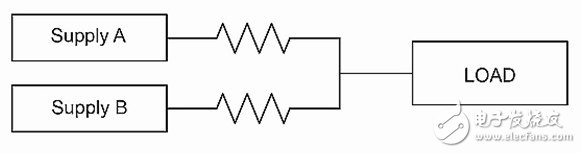
Figure 1: A current sharing method uses a lower value ballast resistor at each power supply output, but this approach is problematic due to resistance-related dissipation and overall efficiency.
What is this "OR"?
One seemingly "simple" solution to direct connectivity is to use a diode connection only between each power supply and the common connection point of all power supplies. This technique is commonly referred to as diode ORing (Figure 2). The ORing diode is very effective in preventing the current from sinking at the connection point, but it is usually not sufficient to solve the current sharing error in the power supply with independent error amplifier, because the conduction characteristic curve of the diode is steep, so that the parameters of the power supply setting value Differences still cause serious current sharing problems.

Figure 2: In principle, it is possible to isolate one power supply from another by using a diode to combine multiple DC power outputs, but this configuration has many performance issues related to load balancing and current sharing.
The diode ORing is generally necessary for the independent operation of the power supply whose output can simultaneously sink and discharge current (dual quadrant operation). Relative to a single-quadrant power supply, if there is no ORing diode, the direct parallel connection of this power supply is even worse. Single-quadrant power supplies have only load-averaged current errors, but regulation of dual-quadrant power supplies produces competitive output voltage control. This will cause large currents that exceed the load current to circulate between the power supplies in the array and may immediately cause one or more power supplies to be overloaded.
Furthermore, if the conduction threshold of the diode is a negative temperature coefficient, this will actually cause current hogging in the array. Rectification with a positive temperature coefficient—a Schottky diode, or a diode-like function built using FETs and rectifiers in an active ORing implementation—is a way to reduce this problem, but due to diode forward voltage drop Efficiency will decrease and active ORing will increase cost and complexity.
In some cases, diode ORing can still improve system-level reliability. The main situation of interest is that one of the power supplies has an output FET or a capacitor short circuit, which can jeopardize the common output voltage rail. The ORing diode quickly isolates the shorted supply from the output for improved reliability and system robustness.
Who is responsible?
In order to achieve reliable and predictable operation in an array, the power supply must generally be designed specifically for parallel operation. We must fully consider startup synchronization, fault protection coordination, and control loop stability.
For a parallel array power supply that provides a higher level of current available to the load, some type of control loop strategy for the array is required. One popular control strategy is to run a power supply without an internal regulated amplifier, but combine them with a common control signal input controlled by an error amplifier. This error amplifier regulates the output of the system and its single feedback signal is distributed to all power supplies in the system.
The main advantage of this popular control strategy is that the output voltage is well regulated, and the current sharing error is determined by the deviation of the modulator gain between the components. The downside is that using a single error amplifier and a single-wire control bus may result in a single point of failure, which can be a problem for certain types of high reliability systems. In addition, the parameter error of the modulator gain is difficult to control, which often causes manufacturers to weigh the yield to control the sharing error.
For a single control loop approach, if the power supply has a small tolerance to its control node input, the current sharing error can be minimized. If the sharing error is large, then the array's power rating must be reduced to avoid any single power supply overload in the array due to shared imbalances, or specific processing is required. Techniques for improving the current sharing error due to differences between different components include calibrating the output error in production (this method is expensive), or adding a current control loop near each power supply in the array to eliminate the error ( This adds complexity and functionality). Current sensing of these local loops typically requires the addition of shunt resistors to the power supply.
For the isolated DC-DC power supply with reference to the primary side of the control node, a second obstacle arises: the transmission of the error amplifier output signal at the primary and secondary side isolation boundaries. Depending on the isolation components used, isolation technology often adds cost, takes up valuable space, and can adversely affect reliability.
The second control loop strategy that allows parallel connections with separate power supplies in the array is to use load lines to emulate the resistance on the path in the ballast resistor approach. By implementing a so-called "droop-share" load sharing method, each power supply has a separate reference and integrated error amplifier, but as the load current increases, the reference voltage is intentionally processed as linear. Reduced so that the output voltage drops by a certain value.
Parallel power supplies can have a negative impact on transient response and load regulation. The buck current sharing method deliberately uses a negative load regulation approach to distribute the load to the modules in the array. Therefore, for a buck current-sharing array, load regulation is often worse than an array created with a conventional single error amplifier. An external control loop can be used around the buck current-sharing array to effectively counteract negative load regulation. Since the external loop itself is an error integrator, the resulting static adjustment error is the same as in the conventional error amplifier.
Power supply design can be simplified while enhanced parallel configuration
Power suppliers can take steps to address the parallel challenge. For example, Vicor's DCM DC-DC converters in converter-package (ChiP) use a built-in negative-slope load line; therefore, as the load increases, the DCM's internal regulator only slightly reduces the output voltage. This is actually like the implementation of a small town flow resistor, but it doesn't use any actual resistors (Figure 3), and it has several other key features.
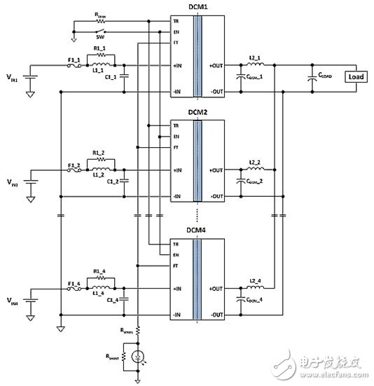
Figure 3: Vicor's DCM in a ChiP package is suitable for paralleling by simply connecting their outputs together; no diodes, ballast resistors, or other load balancing components are required.
First, it is a different way to implement ballast resistors, because there are no physical resistors, and there is no heat generated by V&TImes;I, which does not involve wasting heat. The second difference involves dynamic response, because the frequency is up to hundreds of kilohertz, and since there is no high frequency parasitic problem, the true resistor can be considered to have an infinite "bandwidth" in its IV transfer function curve. Therefore, any transient change in voltage across the resistor will result in a corresponding change in current.
In a DCM converter, the load line is implemented by a discrete time modulator of the digital/analog converter that produces the reference voltage of the error amplifier. The correct reference value is mainly calculated based on the estimation of the DCM output current, and some average processing is done to reduce the noise. Therefore, the load line simulated by DCM is equivalent to a large capacitor in parallel with the resistor. When looking at the data sheet image, the response of the power supply to the step load is due to this RC time constant.
Nonetheless, although this load line output characteristic allows multiple DCM outputs to be directly connected in parallel, their own error amplifier control loops are still active. If all DCMs have the same external (true) path resistance for the load, have the same regulation settings, and are all at the same temperature, the load current distribution on the DCM in the array is exactly equal. Therefore, parallel DCM behaves like a single DCM, but with a higher output current (Figure 4).
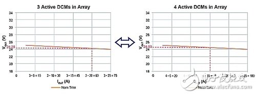
Figure 4: Using a Vicor DCM converter, parallel units can be used as a single converter; in addition, as shown by the load line, if the array has a relative maximum load of N+1 redundancy, the array will continue regardless of any single converter failure. jobs.
Due to its negative voltage temperature coefficient, the temperature variation in the respective units is not a problem with the DCM converter series. If one power supply is loaded more than the other power supplies, its temperature will rise relative to other power supplies, which in turn will cause its output voltage to drop. Since the output voltage of the other parallel DCMs matches the output voltage of the loaded DCM, its output will follow its load line, thereby increasing the sharing of its load current and returning the circuit to equilibrium.
The problems and methods of paralleling DC-DC power supplies are suitable for large converters, such as Vicor's DCM series, and can also be used for much smaller power supply ICs. For example, the LT3083 is a 3A low dropout (LDO) linear regulator from Linear Technology that supports parallel operation of 10 mΩ ballast resistors between each supply and its common output rail.
The use of parallel power supplies is an attractive and viable technology for inventory and procurement, product versatility, additional output current, and N+1 redundancy benefits. However, we must understand the possible parallel topology and how to maintain closed-loop power regulation across multiple power supplies.
16 Port USB 1U Cabinet Charger
Our new 16 port USB1U built -in charger provides the fastest charging, and is supported by tablet computers and other battery -intensive personal electronic equipment! Adopting a compact and lightweight design, without occupying position space, can be a variety of offices, restaurants, retail, education or personal devices configuration. The USB has a built -in fast charging to up to 200 watt charging power, making it very suitable for most tablet computers, smartphones, portable battery charging equipment, and most other devices that meet the USB 2.0. Our new 16 port USB charging hub station has inventory and provides free transportation for free!
Hub USB Charging Station 16 Ports 200W, 16 Port USB Charger 1U Cabinet, 16-Port USB-C HUB
shenzhen ns-idae technology co.,ltd , https://www.szbestchargers.com