An article to understand the principle of motor control and frequency control
Frequency conversion speed regulation is simply to change the frequency and voltage for speed control. The alternating current is converted into direct current by rectification, and the direct current is turned off by the thyristor so that the rectangular wave formed is approximated as an alternating sine wave. The frequent turning off of the thyristor determines the frequency of the output AC. By changing the frequency and controlling the speed change, this is the AC-AC frequency conversion.
The advantages and disadvantages of frequency controladvantage
1, stepless speed regulation
2. Small starting current and large starting torque
3, high speed accuracy
4, easy to achieve automatic control
5, high efficiency
6, energy-saving speed
Shortcomings
1, high cost
2. Generate harmonic pollution grid
3. The output PWM wave will cause extra heating of the motor and cable.
4. The generation of common mode voltage may reduce the life of the motor shaft.
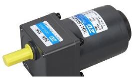
Variable frequency speed regulation is to achieve the purpose of speed regulation by changing the frequency of the motor stator windings. The structure of a commonly used three-phase AC asynchronous motor is shown in Figure 1. The stator consists of a core and a winding, and the rotor winding is made into a cage type (see Fig. 2), commonly known as a squirrel-cage motor. When a three-phase alternating current is connected to the stator winding, a rotating magnetic field is generated in the air gap between the stator and the rotor, which generates a relative motion with the rotor winding, so that the rotor winding generates an induced potential, and an induced current appears. This current and rotation The magnetic field interacts to produce electromagnetic torque that rotates the motor. The rotational speed of the magnetic field of the motor is called synchronous speed and is represented by n1.
N1=60f/p(r/min)(1)
Where: f - three-phase AC power frequency, typically 50Hz.
p - the number of magnetic pole pairs. When p=1, n1=3000r/min; p=2, n1=1500r/min. It can be seen that the more pole pairs p, the slower the speed n1.
The actual rotor speed n is a little slower than the synchronous speed n1 of the magnetic field, so it is called an asynchronous motor. This difference is represented by the slip s:
s=[n1-n)/n1]×100%(2)
When adding the power rotor has not yet turned moments, n = 0, then s = 1; after the start of the extreme case n = n1, then s = 0, that is, s varies between 0 ~ 1. General asynchronous motor under rated load s = (1 ~ 6)%.
Comprehensive (1) and Formula (2) can be drawn
n=60f(1-s)/p(3)
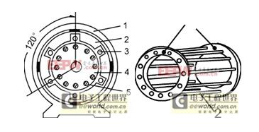
Fig.1 Schematic diagram of a three-phase asynchronous motorFig.2 Rotor winding 1 of a cage motor-Copper ring;2—Copper strip
1—frame; 2—stator core;
3—stator winding; 4—rotor core;
5—Rotor Winding
From equation (3), it can be seen that for the finished motor, the number of pole pairs p has been determined, and the slip rate s has not changed so much, then the speed n of the motor is proportional to the power frequency f, so changing the frequency of the input power can be changed. Synchronous speed of the motor, and then to achieve the purpose of asynchronous motor speed.
However, in order to maintain the maximum torque of the motor at the time of speed regulation, the magnetic flux of the motor must be kept constant. Therefore, the supply voltage of the stator must be adjusted accordingly. The frequency converter is to adjust the voltage (Variable Voltage) while adjusting the frequency (Variable Frequency), so it is abbreviated as VVVF (device). Through the theoretical analysis of electricians, the torque is proportional to the magnetic flux (maximum value). When the rotor parameter is constant, the torque is proportional to the square of the power voltage.
Application of Frequency Control TechnologyLooking at the application of our country's variable frequency speed control technology, in general, we are going from trial to practice, from sporadic to large-scale, from the auxiliary system to the production device, from simply considering energy saving to comprehensively improving the technological level, from manual control to Automatic control, from low to medium capacity to high pressure, in one sentence, from low to high level processes.
Over the years, the State Economic and Trade Commission has been working with the relevant state departments on the development and promotion of frequency control technology, giving priority support in the areas of technological development and technological transformation, organizing the evaluation and recommendation of frequency conversion technology, and promoting the application Frequency control technology as a fan, pump energy saving and technological transformation of the special focus of the investment direction, at the same time encourage the unit to carry out unified loan reunification method, pay attention to the development, grasp the demonstration project, and promote the application. The state has established a fan and water pump energy saving center to carry out information consultation. During the three years from 1995 to 1997, China's fan and pump frequency conversion technology transformation investment capital of 350 million yuan, the transformation of the total capacity of 1 million kw, annual savings of 700 million kw · h, the average investment recovery period of about 2 years.
The application range of frequency control technology has been developed to a new stage. Petroleum, petrochemical, machinery, metallurgy and other industries have undergone three stages of development with single-system trials, large-scale use, and complete plant systems. For example, Guangdong Maoming Petrochemical Company and Jiujiang Petrochemical Plant have now developed the application of atmospheric decompression and catalytic cracking frequency conversion devices, and achieved remarkable results in energy saving and production increase; transportation machinery, air compressors, etc. in 18 specialized plants of Changchun No. 1 Automobile Factory. 162 inverters were used in the equipment to ensure that the production of the new vehicle quickly reached the production target; the Karamay Oilfield in Xinjiang has extensively used frequency converters in oil refining, chemical, water supply, and natural gas processing systems, and the penetration rate of low voltage variable frequency speed regulation has reached 70. %; Meilin Water Plant, Taiyuan Steel Plant, Handan Steel Plant and other units adopt medium-voltage frequency conversion technology on pumps and fan units to ensure production and save energy.
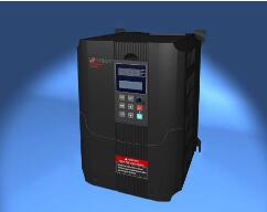
Motor control refers to the control of starting, accelerating, running, decelerating, and stopping the motor. According to the different types of motors and the use of the motor there are different requirements and purposes. For the motor, through the motor control, the purpose of the motor's rapid start, fast response, high efficiency, high torque output and high overload capability is achieved.
The principle of motor control (1)
Motor sequential control circuit
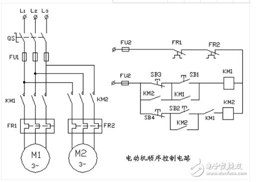
Explanation:
1. The starting sequence of this circuit is the first M1 motor and the rear M2 motor; the stop sequence is the opposite.
2, PLC (Mitsubishi FX0N, FX1N), programmer connection and power operation.
3, clear operation; program write operation; write instruction table according to ladder diagram.
4, the host with a wire connected to the motor sequence control.
The working principle of the motor sequence control circuit: close the power switch QS, press the start button SB1, the contactor KM1 has electric suction and self-protection, M1 motor starts running. The other movable contact of the KM1 is closed, preparing the contactor KM2 for power. Press the start button SB2, the contactor KM2 is sucked and self-protected, and the M2 motor starts running. The starting sequence is KM1 pull-in, M1 motor starts running; after KM2 pulls in, M2 motor starts running. The stop sequence is: Only when the button SB4 is pressed first, the contactor KM2 is powered off and the moving contact of the KM2 is opened. After the M2 motor is stopped and then the SB3 is stopped, the motor M1 can be stopped. The thermal relays FR1, FR2 normally closed contacts protect the motor by automatically disconnecting the control circuit when the motor is overloaded or missing.
The principle of motor control (2)
Asynchronous motor reversible control circuit (example)
Reversible control circuit (example) Circuit working principle:
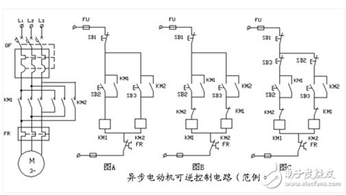
(Picture A) Press SB2, KM1 will pull on electricity, and the motor will start forward. Press SB1, KM1 is powered off and the motor stops. Press SB3, KM2 pulls in electricity and the motor starts to reverse. Press SB1, KM2 is powered off and the motor stops. Disadvantages: Do not press the SB2 or SB3 button at the same time, otherwise the power supply will be short-circuited and the motor will not work. Reason: The main circuit contactors KM1, KM2 are connected to the motor M with two phase sequence power supplies. If they are simultaneously pulled, the power supply is short-circuited at the contact point of the contactor.
(Figure B) The principle is the same as Figure A. In the KM1 coil circuit, a dynamic disconnect contact of the KM2 is connected in series: Similarly, in the KM2 coil circuit, a movable contact of the KM1 is connected in series. These two moving contacts are called interlocking contacts, and this interlocking is called electrical interlocking. Ensure that only one contactor is engaged at any time to avoid a short circuit in the power supply. Disadvantages: The stop button SB1 must be pressed first. After the motor has stopped, the other direction of rotation of the motor can be started.
(Figure C) Based on the above figure, the mechanical interlock consisting of the moving contacts of the start button is added. For example: Press SB2, S2 connected in the KM2 coil circuit breaks the KM2 circuit. Ensure that the two contactors can not pull at the same time, but also can not directly press the stop button to start the other direction of rotation of the motor.
Electrical Products,Upvc Pipe Fitting,Pvc Pipe Fittings,Pipe Fitting Flange,Pipe Clamp Fitting
FOSHAN SHUNDE LANGLI HARDWARE ELECTRICAL CO.LTD , https://www.langliplastic.com