Design of optical and electrical systems for micro-small star sensors based on CMOS APS and SoPC chips
The star sensor is the most sophisticated and drift-free of all sensors, and is an important positioning system in spacecraft. The use of CMOS as a sensor device for star sensors is now the mainstream direction. There is a big gap between domestic star sensors and foreign advanced technologies. With domestically produced devices, microminiature star sensors with independent intellectual property rights have become It is imminent. In this paper, a localized CMOS APS chip and SoPC control chip are used to design the star sensor to study and design its optical and electrical systems.
1 star sensor design
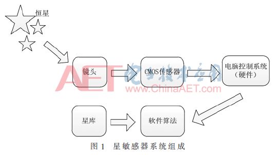
The star sensor system consists of a hood, an optical lens, a sensor chip and peripheral circuits, a data processor and a computer control system. The block diagram of the composition is shown in Figure 1.
1.1 Optical system design
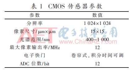
The CMOS APS sensor used in this paper is a domestic model B1XXX. The functions, indicators, parameters, package forms and pin definitions in the circuit are compatible with the most commonly used US CYPRESS STAR1000 products. The parameters are shown in Table 1.
The star sensor optical system parameters will vary according to different application environments. It is mainly determined by the following factors: the cell size of the sensor, the spectral response characteristics, and the highest star to be detected. The parameters of the optical system need to be set with the focal length of the lens, the spectral range, the diffuse spot size, the clear aperture, the central wavelength transmittance, etc. [1].
1.1.1 Determination of the angle of view
The field of view is an indicator that determines the maximum range of stars that an optical lens can detect. Under the same conditions, the larger the field of view, the more stars that can be observed. However, too many stars will interfere with subsequent calculations, so choosing the right angle of view is the first step in building an optical system.
The APS CMOS sensor used in this article is a domestic chip. The cell size is 15 μm, the resolution is 1 024×1 024, and the operating wavelength range is selected from 400 nm to 780 nm. The probability of capturing more than 4 navigation stars in any pose is 99% for subsequent calculations [2]. According to this data requirement, by processing the star catalog, the number of stars and the like can be observed in a given field of view. Further statistics, when the magnitude is 5.5 or the like, the selection of the angle of view of 20°×20° can satisfy the condition that four or more stars are observed in any field of view. Therefore, 20°×20° is selected as the angle of view.
1.1.2 Determination of focal length
The focal length is the distance from the imaging plane to the mirror surface. Since the selected objects are different in distance, the focal length will change accordingly. In space, the position and distance of the stars are relatively fixed, so unlike ordinary camera zoom, the focal length of the star sensor is fixed. The relationship between the field of view and the focal length of the existing optical system is:
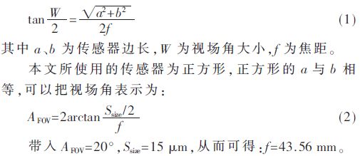
1.1.3 Determination of the size of the speckle
In this paper, taking the angle of view of 20°×20° as an example, using 1 024×1 024 pixels, a single pixel can only reach 20/1 024≈0.019 5°≈70′′. In order to improve the accuracy of pixel measurement. The image received by the sensor needs to be defocused, so that the image points are dispersed, so that the energy is diffused to several surrounding pixels. The energy signals of the plurality of pixels are aggregated, and are calculated according to a certain algorithm. Get the position of the star point. The purpose of this is to make the star point position not only from a single pixel, but to reach the sub-pixel level. That is, the sub-pixel interpolation star point extraction method [3]. The size of the speckle has 2 × 2 pixels or 3 × 3 pixels. The use of large diffuse size can improve the positioning accuracy, but it will affect the subsequent calculation speed. This paper takes 2 × 2 pixel size as the diffuse size.
1.1.4 Determination of relative aperture
The aperture and focal length are represented by a relative aperture F, ie F/#=f/D. In GB/T 30111-2013, the relative aperture is defined as the ratio of the diameter of the entrance pupil to the focal length, ie D/f, which is chosen between 1/0.8 and 1/6.
The calculation of F/# is given by the following formula [4]:
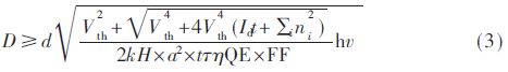
Where Vth is the signal to noise ratio and takes a value of 5; Id is a dark current noise; 
1.2 Electrical system design
1.2.1 CMOS APS sensor analysis
The B1XXX used in this article is a radiation-resistant CMOS image sensor with a resolution of 1 024 × 1,024 with a pixel size of 15 μm × 15 μm. The functions, specifications, package forms and pin definitions of the circuit are compatible with STAR1000 products of American CYPRESS Company. On-chip integration of dual sampling technology, variable gain amplifier (PGA) and 12-bit analog-to-digital converter (ADC). And the on-chip ADC can be electrically isolated, and can use the on-chip ADC digital quantized output, or directly output the optical analog signal according to user requirements.
The circuit has a smart window function, that is, the X and Y addresses of the pixel array can be randomly programmed to realize random control of the window size and the start and stop addresses; and has high sensitivity (≥2.7 V/lux·s (@550 nm)), which can adapt to the space. Low-light environment requirements; with 1, 2, 4, and 8 times programmable gain, can control output gain according to the intensity of light, adapt to a wider working environment; with double-slope integration function, can greatly improve the dynamic range, thereby improving the same environment Adaptability of strong light and weak light at the same time; total radiation resistance capacity ≥100 Krad(Si), single-particle latch-up LET≥75 Mev·cm2/mg.
Device structure and features: The functional block diagram of B1XXX is shown in Figure 2. The image sensor consists of six main components: pixel array, addressing logic, pre-amplifier, programmable gain amplifier (PGA), analog multiplexer, and ADC.

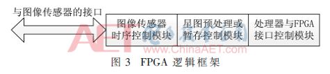
1.2.2 FPGA Timing Driver Module
The choice of focal plane image sensor is directly related to the core design of the star sensor.
The system uses FPGA to implement the driving of CMOS image sensor, the interface between CMOS image sensor and processor system, and the function of star map storage or star map preprocessing. The single-clock fully synchronized design is used in the design. The external 20 MHz crystal provides the clock input source and the internal divides the frequency. This more complex timing logic can be implemented by programming [5], as shown in Figure 3.
1.2.3 Signal Processing Solution
The signal processing board adopts the domestic SoPC core signal processing board. The core board is based on the domestic SoPC for secondary integration development. The SoPC minimum application system, basic configuration circuit and communication interface module are integrated into a small SoC with a size of 51.4 mm×51.4 mm. On the board. The overall block diagram of the SoPC chip is shown in Figure 4.
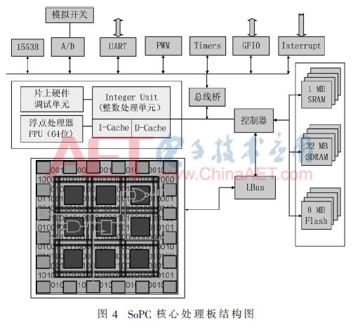
In addition, the core signal processing board also includes the basic configuration and communication interface with the application system, including: PLL configuration, debug interface configuration, reset module, clock module, FPGA configuration, and so on. The communication interface mainly includes: 1553 communication interface, ADC interface, serial communication interface, expandable GPIO interface, interrupt interface, I2C bus, timer/counter input/output interface, test and indication interface, and the like. These basics can meet the software requirements of the star sensor.
The final design is to miniaturize the size of the star sensor electrical system (without housing) to 60 mm × 60 mm, the total weight of the two boards (including fasteners) is about 60 g, and the static power consumption is about 1.2 W.
2 APS Star Sensor Software Solution
The software algorithms of the star sensor mainly include the establishment of star library, star map preprocessing, star map recognition and star map matching, and attitude solution.
(1) Star library establishment
The star library is a collection of navigation stars created after filtering according to the catalog, and its role is to provide a basis for matching when performing star map matching. Once you have determined the star catalog, you can create a corresponding navigation star library based on the catalog.
(2) Star map preprocessing
After the sensor obtains the image, due to the presence of various noises, it is necessary to perform noise reduction before processing the data, and then extract the star point centroid and provide it to the star map recognition algorithm.
A simple average denoising method is used in practical applications. Since the value of the fixed noise is irregularly presented within a certain range, the average value can be taken as the fixed noise of the system, and then the difference between the acquired image and the average value can be used to obtain a preliminary noise reduction effect. The specific method is: using a star sensor system to continuously take pictures in dark conditions, and obtain information on noise, including position and value. The noise information obtained at the same position is calculated by the average method as its final value.
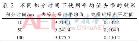
Due to the different integration time, the noise presented by the fixed noise will be slightly different. The difference between the average noise and the actual value obtained by the 10 average method is counted in the case where the integration time is 10 ms, 50 ms, and 100 ms.
When collecting all black pictures, fixed noise interference can affect about 3.6%. The noise gray value is concentrated around 08~10. When the average denoising method is used, the noise gray value is concentrated around 00 to 02. Table 2 shows the effect of using average denoising at different integration times.
(3) Star map recognition and star map matching
After extracting the centroid information, the navigation star library is searched for a navigation star that recognizes the same information, and if a unique matching navigation star is obtained, the matching is successful.
(4) Attitude solution
When the matching is successful, the posture is solved, the current attitude angle or quaternion data is calculated, and the result is output.
Figure 5 is a flow chart of the star sensor software.

3 Conclusion
Based on a domestic anti-radiation COMS APS chip and SoPC control chip, the optical and electrical systems of micro-small star sensors are designed. According to the existing sensor characteristics, the appropriate optical system parameters are selected in a targeted manner, and the determined parameters are obtained. After determining the angle of view and the APS sensor, the optical system can sequentially obtain parameters such as focal length and relative aperture. The star sensor designed the FPGA driver module and signal processing module according to the requirements of hardware and system. The star sensor hardware is completely domestically self-contained and meets the requirements for star sensors in GB/T 30111-2013. The software part is programmed according to the existing device parameters. Finally, a set of experimental prototypes of localized star sensor experiments was designed and completed.
Absolute rotary Encoder measure actual position by generating unique digital codes or bits (instead of pulses) that represent the encoder`s actual position. Single turn absolute encoders output codes that are repeated every full revolution and do not output data to indicate how many revolutions have been made. Multi-turn absolute encoders output a unique code for each shaft position through every rotation, up to 4096 revolutions. Unlike incremental encoders, absolute encoders will retain correct position even if power fails without homing at startup.
Absolute Encoder,Through Hollow Encoder,Absolute Encoder 13 Bit,14 Bit Optical Rotary Encoder
Jilin Lander Intelligent Technology Co., Ltd , https://www.jllandertech.com