Laser processing technology for high-density PCB manufacturing applications, improving the efficiency of microporous drilling
Most electronic components require an input power source from the AC power line. For voltage regulators, switch mode power supplies, and other downstream electronics, a full-bridge or half-bridge diode rectifier device rectifies the sinusoidal AC voltage waveform and converts it to a DC voltage.
The use of four diodes in a bridge rectifier configuration is the simplest and most conventional method of rectifying AC voltage. Running a diode in a bridge rectifier provides a simple, cost-effective and zero quiescent current solution for full-bridge rectifiers and automotive alternators.
However, although diodes typically have the fastest response to negative voltages, they can cause higher power losses due to positive and negative junction forward voltage drops (Vf ~ 0.7V). These power losses can cause heat and require designers to perform thermal management, which increases system cost and solution size. Another disadvantage of diodes is the high reverse leakage current—up to about 1 mA.
Replacing a high-loss diode with an N-channel MOSFET can significantly reduce power loss by eliminating the forward voltage drop of the diode rectifying device. N-channel MOSFETs have small RDSON and their associated voltage drop is also minimal.
Table 1 compares a 5A (I_rms = 3.5A) diode rectifier with a 10mΩ MOSFET-based rectifier device.
Table 1: Comparison of MOSFET and Diode Power Loss

Clearly, when using MOSFETs, the power loss is incredibly small, and designers don't have to use expensive and bulky heat sinks for thermal management. However, everything has a price. N-channel MOSFETs require a gate drive to conduct current from the source to the drain and need to be turned off quickly when the AC sine wave becomes negative. By combining an N-channel MOSFET with four LM74670-Q1 smart diode rectifier controllers, the MOSFET gate can be turned off during the negative period of the sine wave. The LM74670-Q1 is designed to drive each N-channel MOSFET separately to simulate an ideal diode with no forward conduction losses. The LM74670-Q1 uses a floating topology and charge pump for true diode replacement.
Figure 1 shows the LM74670-Q1 operating in a full-wave bridge rectifier design.
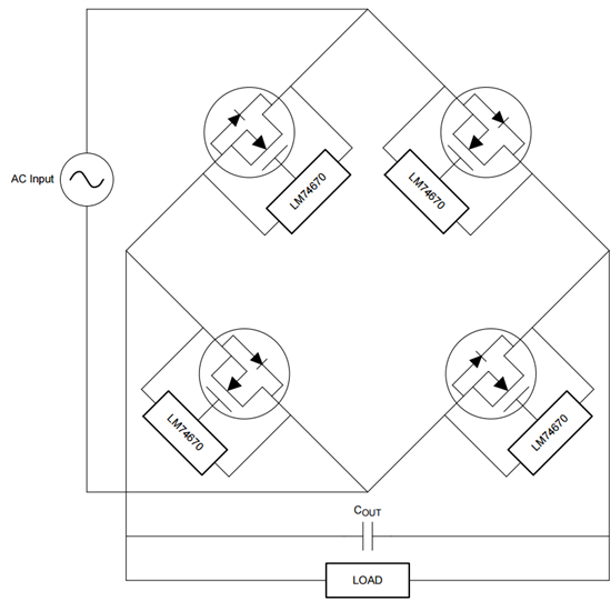
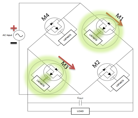
Figure 1: The LM74670-Q1 Smart Diode Bridge Rectifier operates in this bridge rectifier method. Each diode is replaced by the LM74670-Q1 solution, which includes an integrated circuit MOSFET and a charge pump capacitor. Each solution operates independently and responds to the AC input waveform like a diode. The LM74670-Q1 continuously senses the voltage across the MOSFET with the anode and cathode pins and turns the MOSFET gate on and off based on the voltage polarity. During the positive period of the AC waveform, as shown in Figure 2, MOSFETs M1 and M3 are conducting, while the gates for M2 and M4 are turned off by the corresponding LM74670-Q1.
Figure 2: Forward conduction in the positive cycle of the AC input
When the AC waveform becomes negative, the LM74670-Q1 corresponding to M1 and M3 respond to the negative voltage for 2 μs and turn off the gates of the two MOSFETs. During this time, as shown in Figure 3, the M2 and M4 MOSFETs are turned on.

Figure 3: Forward conduction in the negative cycle of the AC input. The MOSFET used in this application must have a gate-to-source voltage (VGS) threshold of 3V or less, and a low gate capacitance. Another important electrical parameter is the voltage across the body diode of the MOSFET. This value must be around 0.48V at low output current. The Texas Instruments 60V CSD18532KCS N-Channel Power MOSFET or other NexFETTM MOSFET is the best choice for this application.
Figure 4 shows an oscilloscope plot for a smart bridge rectifier based on the LM74670-Q1 with four CSD18532KCS MOSFETs. This rectifier is powered by a 12V 60Hz AC input supply, which in this example produces a rectified output. The VGS for MOSFET M1 shows how the LM74670-Q1 controls the forward conduction through the MOSFET and how to turn off the reverse voltage by turning off the gate.
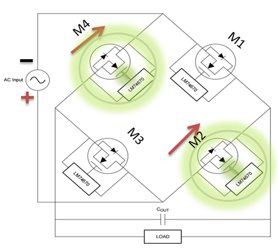
Figure 4: LM74670-Q1 Smart Bridge Rectified Output Figure 5 compares the LM74670-Q1 Smart Bridge Rectifier (equipped with four CSD18532KCS N-Channel MOSFETs) (left) with a conventional low forward voltage drop diode (Vf = Thermal performance between the 0.5V) rectifier (right). Both designs operate at high current (10A) with no thermal management and air flow. The temperature of each diode in a diode rectifier reaches approximately 71 ° C, while the temperature of the CSD18532KCS MOSFET in the LM74670-Q1 rectifier is approximately 31 ° C under the same operating conditions.
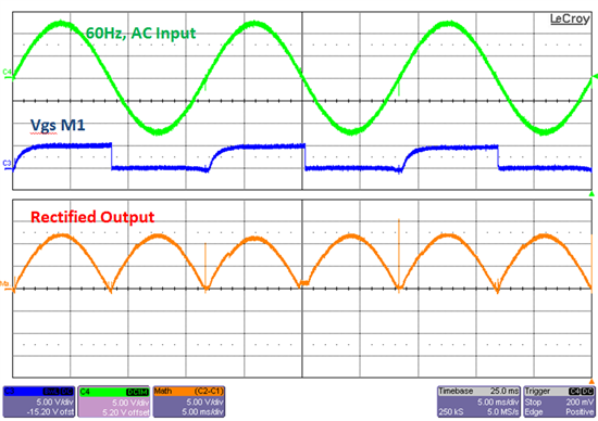
Figure 5: Thermal Performance vs. a Conventional Diode Rectifier In summary, the LM74670-Q1-based smart diode full-bridge rectifier design has these features and benefits:
Increased system efficiency by approximately 10 times.
The MOSFET does not require any thermal management for high current applications.
This design reduces system cost and reduces space on the printed circuit board.
Supporting higher frequencies up to 400Hz and AC voltage levels up to 45V make it a suitable replacement for automotive alternator applications.
Sensor Kit,Sensors Modules Kits,Sensor Test Kits,Sensor Electronic Kit
Cixi Zhongyi Electronics Factory , https://www.zybreadboard.com