What is the principle of 51 MCU clock circuit? Detailed picture and text
The clock circuit is an oscillator that provides a beat to the single-chip microcomputer, and the single-chip microcomputer must perform various operations under the control of this beat. Therefore, the single-chip microcomputer will not work normally without a clock circuit. The clock circuit itself does not control anything, but you let the MCU do the corresponding work according to the clock through the program.
There is a high-gain inverting amplifier in the MCS-51 single chip microcomputer. The input of the inverting amplifier is XTAL1 and the output is XTAL2. The oscillator circuit and clock circuit formed by this amplifier together form the clock mode of the single chip microcomputer. According to the different hardware circuits, the clock connection mode of the one-chip computer can be divided into internal clock mode and external clock mode, as shown in Figure 1.
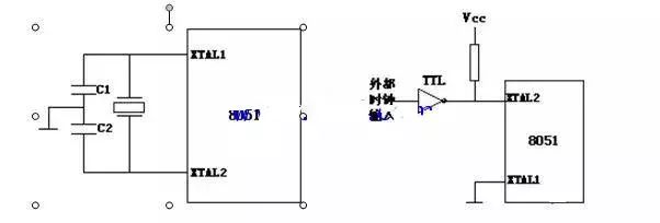
(A) Internal clock circuit (b) External clock circuit
Figure 1 Clock circuit
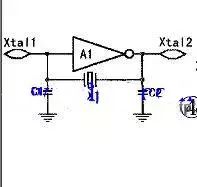
Schematic diagram of internal clock (that is, a self-oscillation circuit)
In the internal clock circuit, a quartz crystal oscillator and two trimming capacitors must be connected across the XTAL1 and XTAL2 pins to form an oscillator circuit. Usually C1 and C2 are generally 30pF, and the frequency of the crystal oscillator is between 1.2MHz and 12MHz. between. For the external clock circuit, XTAL1 is required to be grounded, and XTAL2 is required to be connected to an external clock. There are no special requirements for external clock signals, as long as a certain pulse width is guaranteed and the clock frequency is lower than 12MHz.
The oscillation signal of the crystal oscillator is sent from the XTAL2 end to the internal clock circuit, which divides the oscillation signal by two to generate a two-phase clock signal P1 and P2 for the single-chip microcomputer. The period of the clock signal is called the state time S, which is twice the oscillation period. The P1 signal is valid in the first half period of each state, and the P2 signal is valid in the second half period of each state. The CPU uses the two-phase clock P1 and P2 as the basic beat to coordinate the effective work of each part of the microcontroller.
M40 stainless steel series power connectors are specially developed products for applications in strong corrosive environments. Manufactured from high-grade stainless steel and advanced polymers, this series of M40 Connector is ideal for use in the harshest industrial processing environments. In addition to specialized materials, these M40 Power Connector assist in industrial processes by featuring a smooth outer body design that prevents the ingress of dust and contaminants. These connectors are designed to perform well under harsh environmental conditions with a rugged backshell, high-reliability contact technology, and simple assembly procedures. Custom solutions and platform products are designed with modular or round bodies, ensuring a perfect fit in industrial environments where connectors are required to manipulate, control, power or monitor equipment.


M40 Connector,6 Pin Power Connector,M40 Power Connector,M40 Connector 8 pin, M40 motor connector
Kunshan SVL Electric Co.,Ltd , https://www.svlelectric.com