Teach you a few coups to recognize transmission lines
All kinds of wires, you can't see them when you look up, but I dare to bet with you, you don't necessarily know them!

What is the voltage, DC or AC... 90% of the people are immediately dumbfounded...
Even people who study electricity and work in the power system do not necessarily know transmission lines...
Today, I will teach you a few coups for recognizing transmission lines.
Transmission line
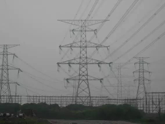
Let me talk about the concept of power transmission towers. Transmission wires are supported section by section. For high voltage levels, use "iron towers", and for low voltage levels, such as those found in residential areas, generally use "wood poles" or "cement poles." , Collectively referred to as "pole tower". Lines with high voltage levels need to have a greater safety distance, so they must be erected very high. Only the iron tower can afford lines of tens of tons. A telegraph pole cannot be erected this high and does not have such a large supporting force, so the wire The rods are all of a lower voltage level. As for how high the voltage is high and how low is low, let’s go back and elaborate.

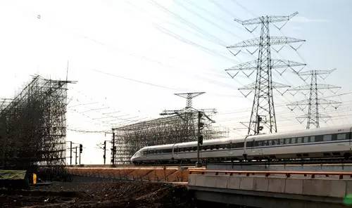
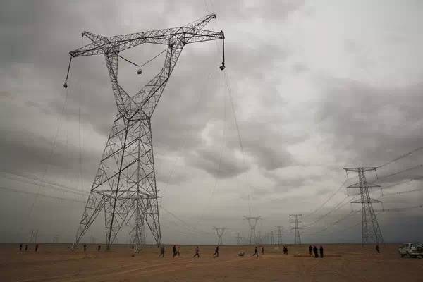
(1000 kV UHV AC line sent from Anhui to East)
By the way, the voltage level refers to the line voltage, the voltage between any two of the three phases ABC. The 220 volts used at home is the phase voltage, which is the voltage of any one of the three phases relative to the earth. The actual electricity consumption at home is 380V line voltage (three times the root number of 220V), but the three phases are separated when the door of the building is reached. For example, the three phases of ABC enter three units in a building. The 380V voltage level is also called 0.4kV voltage level in the power system. Compared with the current 1000kV UHV transmission line, the difference is 2500 times, and it is trembling~
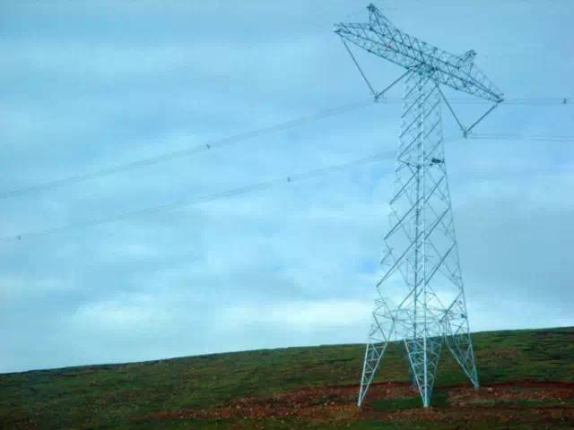
The transmission towers we saw along the way were generally transmission towers. As for the tower type, it’s meaningless. The cat’s head tower, wine glass tower, gate tower, and V-shaped tower are all "pictograms". know. Transmission lines are also divided into DC and AC (DC and AC). DC is easy to recognize but not very common. There are only a few domestic lines and it is not easy to run into them.
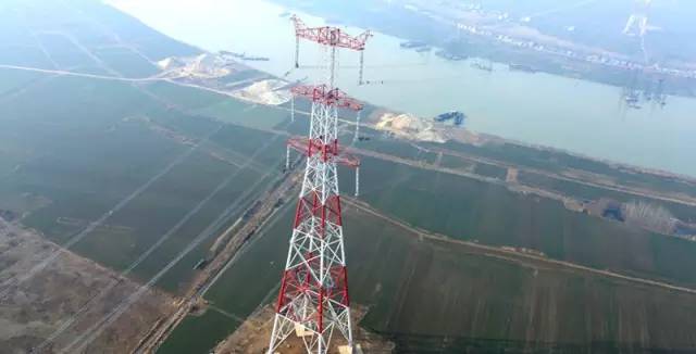
The picture below shows the ±800 kV South Hami-Zhengzhou UHV DC transmission line
The tower is T-shaped, and there are two transmission lines hanging underneath, with one positive pole and one negative pole. As for why the positive pole and the negative pole are divided into so many strands, let's wait until we talk about the split wires of the AC line. Take a closer look at the two small "corners" protruding from the tower, with a "thin wire" on each side. This is not for power transmission, but a lightning wire for lightning protection, also called a ground wire.
The following will focus on the exchange line, this is almost "Dabao see you every day".
AC line
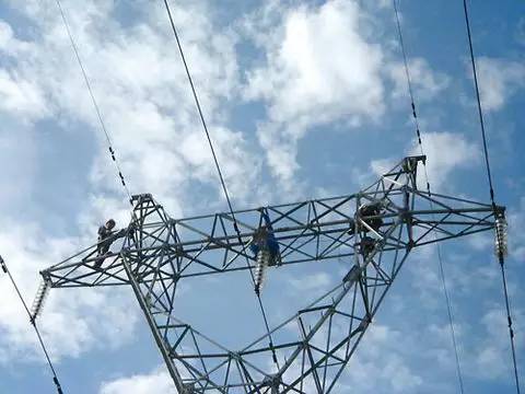
The AC line has three phases A, B, and C, and the top of the transmission tower is a lightning protection line. In areas with frequent thunderstorms or lines with high voltage levels, there are two lightning protection lines. Lines with less severe thunderstorms or low voltage levels can be reduced to one lightning protection line. This is selected from the perspective of engineering practice and money saving. Anyway, everyone sees the most One or two thin wires at the top are known as lightning protection wires.

The lightning protection wires are connected to the iron tower in order to lead the electric current during the lightning strike to the ground along the iron tower. However, when connecting, there is a section of insulator or insulator between the lightning conductor and the tower. If you look carefully, you can see the jumper. The purpose of this is to facilitate breakdown and leakage during lightning strikes, while reducing power transmission losses in normal times. If the lightning protection wire is directly connected to the iron tower, the induced current to the wire in the wire will directly flow into the ground, causing transmission loss.
Lightning lines are generally used for transmission towers in open areas with high voltage levels. Generally, there are very few lightning lines on the poles we see: one is that the poles are generally in cities, and there are other higher buildings that can be struck by lightning; The second is that low-voltage poles can't deliver much electricity, and the cost of installing a lightning protection wire is high.
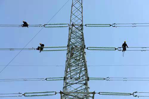
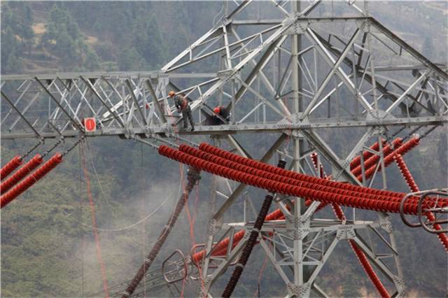
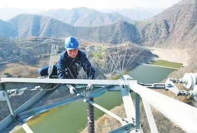
Below the lightning protection line is the transmission line. The number of lines is a multiple of 3. The three lines are called one loop line, the 6 lines are called two loop lines, and the 12 lines are called four loop lines. Three wires of ABC three-phase. The picture at the beginning is called the "Four Circuits in the Same Tower" route. The reason why there are multiple circuits on a tower is mainly due to the transmission capacity and floor space, so the concepts of "line length" and "loop length" are also derived. For double circuits on the same tower, the circuit length is the length of the circuit 2 times of, and so on. The following figure is also two lines with four circuits on the same tower. If they are of different voltage levels, the voltage of the upper wire is higher than the voltage of the lower wire. The higher the voltage, the higher the safety distance requirement to the ground.
Two different layouts of four-circuit lines on the same tower
In fact, lightning protection wires and transmission wires are also very easy to distinguish. One is directly on the tower, and the other needs to be suspended on the tower with insulator strings. There is ground potential on the tower. Without the insulation of the insulator string, the wire is directly short-circuited to the tower. Looking at the transmission line, it is the first to be able to distinguish the voltage level, which determines which line it is, how much power and how far it is transmitted.
How do you see the voltage of the transmission line at a glance? The secret is "three look": look at the number of wire splits, look at the length of the insulator string, and look at the height of the tower.
1
Look at the wire split
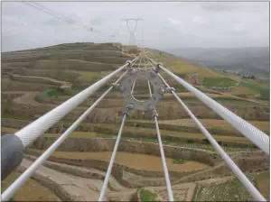
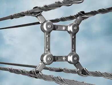
Let’s talk about the number of splits. As shown in the picture below, for each phase of the ABC three-phase conductors, it is divided into several strands. For example, the following 1000 kV UHV transmission line is divided into 8 strands, which is called "eight splits." "wire. The reason why a wire of one phase needs to be split into several strands is to enlarge the "equivalent diameter" of the wire, which is equivalent to using several thinner wires (relatively thin, in fact, there are girls’ wrists thicker), enclosing an approximate circle The shape is equivalent to an "equivalent" enlargement of the diameter of the phase-integrated wire.
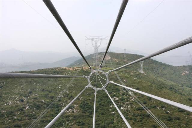
There are several reasons for expanding the "wire diameter":
One is that alternating current has a "skin effect". Because of self-inductance, most of the current flows on the surface of the wire. There is almost no current in the conductor. Making the conductor into a tube can simplify the material and reduce the weight. Since it is a tube, it is better to split it. Wire instead of tubular wire;
The second is that the high-voltage transmission line has a large current and requires low resistance of the wire. The resistance is inversely proportional to the area of ​​the wire. Therefore, it was originally replaced with a very thick tubular wire, but now it is split wire (in the substation, the tube bus is still used);
The third is that the thicker the wire, the lower the electric field intensity on the wire surface and the smaller the corona. Corona is a loss of electrical energy. Of course we hope to make the wire thicker to reduce the surface field strength and corona.
Corona is a discharge phenomenon. You may hear a "zzi" sound around transmission lines in rainy days. That is the sound of corona. You can also see the wire glowing weakly at night. Of course, corona is not only harmful. , I can elaborate on it later.
The "zzi" sound of the corona can also cause radio interference, which is why the DC wire is split, all to reduce the corona.
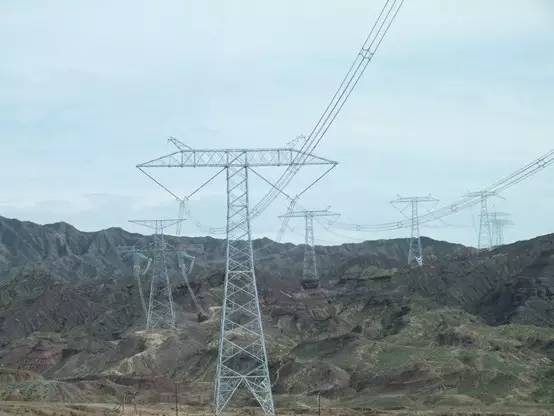
There are 750 kV ultra-high voltage transmission lines below 1000 kV. This voltage level is only used in my country's Northwest Power Grid. There are also lines with a voltage level of 765 kV in Europe. 750 kV voltage level generally uses six-split wires.
500 kV is a four-split conductor according to the regulations, but according to observations, six-split conductors are now the majority, especially in the periphery of large cities, where the transmission power may be higher.
220 kV is generally divided into two parts. For voltage levels of 110 kV and below, there is no need to split the wire. A single wire will do. The corona is not serious.
However, due to the large transmission power, 220 kV four splits and 110 kV two splits can also be seen in some places. There are three-split wires in theory, but I haven't seen them much.
2
Look at the number of insulators
What is an insulator? Look at the long green glass in the red circle in the picture below, which is an insulator.
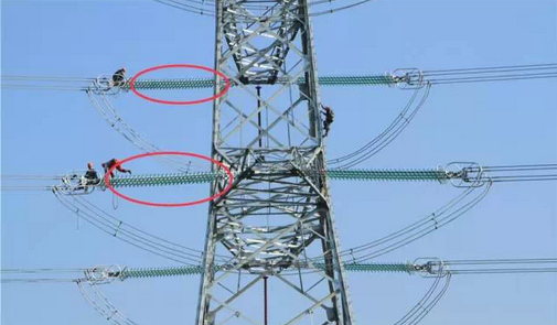
An insulator is a special insulation control, usually made of glass or ceramic, to increase the creepage distance. Its shape is like a flying saucer. A flying saucer is considered as a piece of insulator. The insulator string is used to string together several flying saucers to isolate the wires from the tower. The figure below is the shape of a piece of FRP insulator.
Let's talk about the number of insulators. The number of wire splits is relatively easy to count. You can know the high voltage level by counting the wires. In addition to looking at the number of splits, you can also count the number of insulators, but it is more eye-intensive. If you are familiar, you will know at a glance.
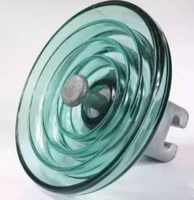
The commonly used insulators are ceramic insulators. The figure below shows ceramic insulators and composite insulators.

The approximate thickness of a piece of insulator is 15 cm, and a string of 7 pieces is almost one meter.
In general:
750 kV, 32
500 kV, 23-25
330 kV, 17
220 kV, 13
110 kV, 7
66 kV, 5
35 kV, 3
If there are high altitudes, heavily polluted areas or important towers, the number of slices should be increased by a few more. It can basically be seen that a piece of insulator can withstand a voltage of 1-1.5 million volts, but as the voltage level increases, the nonlinearity of the pressure is stronger. In fact, the number of insulators may vary greatly in different regions and environments. Of course, the number of pieces required for different types of insulators is also different. The picture below is a 1000 kV UHV diagram. The power grid master counted it with the naked eye. It is about fifty or sixty pieces. It is really long...
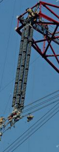
1000 kV AC UHV line insulator
±800 kV UHV DC line insulator
3
Look at the height of the tower
In addition to counting the number of splits and the number of insulators, you can also look at the height of the tower. Although the design regulations do not specify how high the tower should be, it specifies the minimum distance between the transmission conductor and other objects in great detail.
(500 kV line tower)
The first gear of the transmission line is about 500 meters, and the wires have to sag, especially when the weather is hot and the power load is heavy, the wires will expand and contract with heat, which will sag even more. Therefore, the minimum distance between the conductors of the transmission lines of each voltage level and various objects is clearly written in the regulations.
For example, the minimum distances between the conductors and the ground in residential areas are:
35~110 kV is 7 meters,
220 kV is 7.5 meters,
330 kV is 8.5 meters,
500 kV is 14 meters,
750 kV is 19.5 meters.
(750 kV line tower)
If the wire sag and the length of the insulator are considered, then:
110 kV is about ten meters above the ground,
220 kV and 330 kV are more than 20 meters,
500 kV is thirty or forty meters,
750 kV is more than fifty meters,
1000 kV is seven or eighty meters.
(1000 kV UHV line tower)
Converted to the height of the building, they are 5 floors, 8 floors, 12 floors, 18 floors, and 25 floors, which is a bit of an impression. But this is very rough, according to the climate and terrain, the height has to be adjusted greatly.
Generally speaking, the easiest way to distinguish voltage levels is the number of wire splits, the most accurate judgment is the number of insulators, and the most shocking thing is the height of the tower.
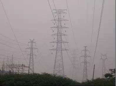
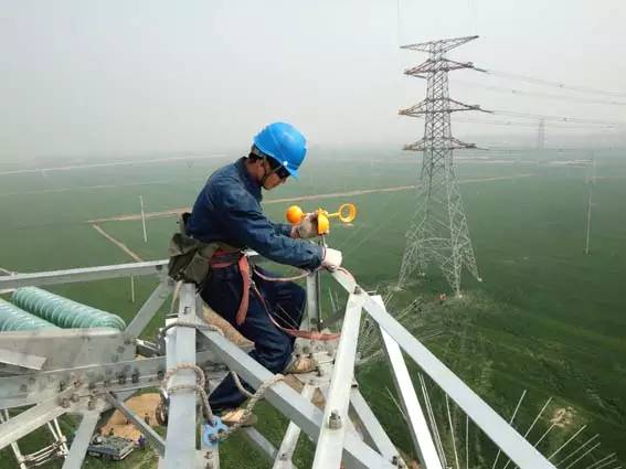
The transmission lines we can see are all areas with relatively good topography. We must know that there are transmission lines in the mountains and rivers, especially for remote areas. The iron towers and wire materials are all carried by people. Yes, very hard! It can be said that there may be transmission lines where there are no roads. I really want to pay tribute to the power transmission and transformation staff!
Finally, talk about the gadgets on the transmission tower. Look! Guess what this prickly and orange little windmill is for?
Anti-bird thorn
The answer is revealed: they are all bird-proof! Barbs are used to prevent birds from building nests and are used on iron towers; small windmills are used to drive away birds and are generally used on telephone poles. You can pay attention next time!
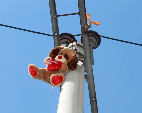
(One day in a certain year, when I went out and looked up, I found a teddy bear on the pole, which is said to be a bird repellent, and he vomited three liters of blood...)
Why can't the transmission towers get through with the birds? Because bird droppings are an important cause of short-circuit failures in transmission lines. Bird droppings are conductive. When discharged on the insulator string, they will form a short-circuit path for the wires to the ground. Therefore, the transmission lines are very afraid of "angry birds"...
In addition to birds, snakes, rats, weasels, or large birds with long wingspans can all cause short circuits to ground or phase to phase. Big trees will do too, so you should trim trees regularly.
Filter mesh refers to small aperture metal mesh or other materials with smaller apertures for a variety of different filtration, dust removal and separation requirements. They are widely used in shower panel, sanitary pipe systems, purifiers, electronic components, to remove contaminants or in applications, such as coffee machine, soya milk machine, to extract a filter cake. Because the metal mesh filters are one of the most durable filter media available, the material is mainly made of copper, iron, steel, nickel, stainless steel, alloy. It is acid resistant, alkali resistant, temperature resistant and wear resistant.
We customize diverse patterns metal microporous mesh with drawings provided by customers. We are equipped with professional metal etching equipment and exposure development equipment. Chemical metal etching filter mesh is a double-sided and simultaneous processing technology, which can make the product surface (positive and negative) smooth, without bumps, pits, burrs, warps, and flat mesh without deformation. Below are the advantages for customized metal filter mesh:
Flow Rate
One of the most significant advantages metal mesh has over most filter media used today is its ability to deliver an adequate flow rate. This is achievable as the wire diameter and mesh opening can be customized to perfectly match the contaminants you are filtering out, providing you with an enhanced level of filtration surface area.
Durability
300 series stainless steel is predominantly used. This helps create a filter that can withstand a wide range of impurities, pressure variations, and extreme temperatures without hindering the filter's accuracy. In addition, stainless steel is a very pliable material, allowing the filter to be formed to fit your filter system and hold its shape after several uses.
Accuracy
The weaving process used to construct mesh filters is heavily monitored from start to finish. As a result, the pore openings of the filter are exact and uniform throughout the filter. These precise pore opinings ensure that the end product, whether a filtered substance or a filter cake, is consistent and complies with industry standards.
Clean ability
As metal mesh features accurate pore openings, blinding and plugging are significantly reduced. This, combined with the enhanced flow rate, means system operators can clean the metal mesh easily. These two properties allow the mesh filter to be backflushed and purged of any unwanted debris with minimal pressure.
Metal Etching Filter Mesh,Metal Filter Mesh,Metal Microporous Mesh
SHAOXING HUALI ELECTRONICS CO., LTD. , https://www.cnsxhuali.com