A detailed collection of 11 motor drive designs
24V Brushless DC (BLDC) Motor Sine Wave Drive for Air Purifier Fan
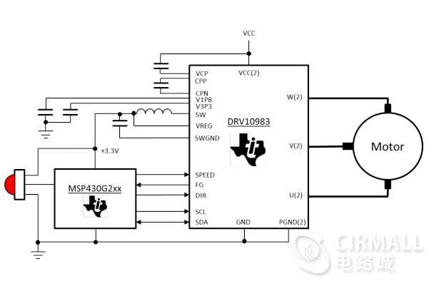
This reference design is an affordable, small form factor (SFF), three-phase sinusoidal motor drive for brushless DC (BLDC) motors, delivering up to 50W at 24V. This board accepts 24V input and provides three motor outputs to drive BLDC motors sinusoidally. After accepting the speed command through the IR (infrared) sensor, the speed loop is closed externally using a microcontroller (MCU) (MSP430G2303 in this design).
BLDC motor sinusoidal drive characteristics:
Capable of driving brushless DC (BLDC) motors with sinusoidal commutation as a 50W, 24V driver
The role of MSP430G2303 is to accept IR input and close the external speed loop
The DRV10983 uses a proprietary sensorless control scheme to provide continuous sinusoidal drive, significantly reducing the pure tones typically generated during commutation
Powers internal and external circuits (TI MSP430â„¢ MCU in this design) by efficiently reducing the supply voltage to 3.3V with an integrated buck/linear regulator
Hardware design tested at 50W for good thermal performance
This design is a tested, ready-to-use hardware and software platform for driving 12V/24V, less than 50W BLDC motors
Design block diagram of a brushless DC (BLDC) motor sinusoidal drive system:
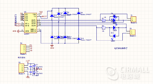
Motor sinusoidal drive experimental circuit board display:
STM32 stepper motor H-bridge drive control schematic + source code
The content of the attachment shared is the open source data of STM32F103VCT6+ stepper motor L6205H bridge drive control.
What can you learn from the STM32 stepper motor driver?
1. Basic program structure what should be placed in MAIN and what should be placed in interrupt
2. STM32 + DMX512 receiving program or (RS485)
3. Photoelectric encoder program (without open-loop control)
4. FSMC TFT driver with menu function
5. Stepper motor subdivision driver vector control acceleration and deceleration control, PWM chopper drive mode.
6. Multiple timer operations, PWM control external interrupt input serial port interrupt and long and short keys, code protection.
7. How to operate printf and TFT LCD debugger.
Screenshot of the STM32 stepper motor drive development board:
STM32 stepper motor driver source code screenshot:
(Infineon) electric bicycle, small electric vehicle, motor control board + BLDC motor driver (schematic diagram + PCB + design description)
Universal motor driver card designed for use with the CPU board of the Infineon XMC4000 microcontroller family. This satellite card is part of the Infineon Hex Application Kit family with a suitable CPU board to demonstrate the motor control capabilities of the XMC4000 series.
The actual motor control board circuit:
Motor control board circuit characteristics:
· Seamless connection to CPU board via ACT satellite connector
3-phase low-voltage half-bridge inverter using Infineon MOSFET power transistors
Gate driver IC with overcurrent detection circuit (ITRIP)
Use a single or triple shunt (amplified) to measure current
Position sensing via inductive resolver, quadrature encoder or Hall sensor interface
·Input power range: 24V +/-20%
On-board power supply includes SMPS for 5V power generation with LDO regulator for MOSFET gate driver and resolver excitation (15V) and logic (3.3V)
Motor control board circuit parameters:
Stepper motor driver schematic + PCB + driver source code + tutorial, etc.
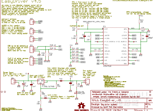
The stepper motor driver is also called EasyDriver. The EasyDriver can provide about 750mA per phase (1.5A total for both poles) for the two-stage stepper motor. It defaults to 8 step subdivision mode (so if your motor is 200 steps per revolution, it defaults to 1600 steps per revolution when you use EasyDriver), more subdivision modes can be done by grounding both pins MS1 or MS2 set up. This is a subdivision circuit breaker based on the AllegroA3967 driver chip. For full specifications of this design, please consult the parameter sheet for the A3967. Its maximum current per phase is from 150mA to 750mA. The maximum drive voltage that can be used is about 30V, including the onboard 5V regulator, so only one power supply is required. Good quality and cheap, this thing is only a dozen bucks, which is cheaper than making your own circuit boards.
Stepper motor driver design features:
·A3967 Microstepping Driver
MS1 and MS2 pins broken out to change microstepping resolution to full, half, quarter and eighth steps (defaults to eighth)
Compatible with 4, 6, and 8 wire stepper motors of any voltage
·Adjustable current control from 150mA/phase to 700mA/phase
·Power supply range from 6V to 30V. The higher the voltage, the higher the torque at high speeds
Screenshot of the schematic diagram of the stepper motor driver:
Physical display:
Screenshot of stepper motor driver driver source code:
[Open Source] Multifunctional Stepper Motor/DC Motor Controller Development Board (Schematic + PCB + Sample Program + Component List)
This is a multi-function motor control development board that integrates motor control and microcontroller development. It can not only realize the drive control of stepper motors and DC motors, but also can be used as a common 51 development board. The attachment provides detailed schematic diagrams and PCB engineering files, which can be directly sent to the factory for production. The board adopts the powerful and easy-to-use AT89S52 single-chip microcomputer as the main control chip, and the motor drive part uses the L298N driver, which can easily control the general motor control, including the realization of motor forward and reverse rotation, PWM speed regulation, etc. In addition, the attached sample program provides detailed sample programs for each function, which is convenient for friends to refer to and learn.
Stepper Motor Reference Routine Package:
DC Motor Reference Package:
Stepper motor wiring:
DC motor wiring:
48V 1kW automotive three-phase brushless DC motor driver design (schematic diagram, PCB source file, source program, etc.)
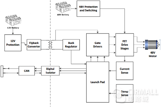
The TIDA-00281 TI reference design is a three-phase brushless DC motor driver for 48V automotive applications. The board is designed to drive motors in the 1kW range and can handle up to 30A. This design uses an analog circuit used with the C2000 LaunchPad to rotate a three-phase BLDC motor without position feedback from Hall-effect sensors or quadrature encoders.
Design block diagram of automotive DC motor driver system:
Three-phase brushless DC motor driver circuit characteristics:
Speed ​​control of three-phase brushless DC (BLDC) motors without position sensors
Control of three-phase power supply through phase voltage and current sensing scaling and filter feedback
Works over a wide voltage range of 48V battery systems
Reverse polarity protection for 12V battery
Three-phase brushless DC motor driver circuit board PCB screenshot:
Attachment content screenshot:
MOS dual motor drive module BTS7960 data summary (schematic diagram, test program, operating instructions, etc.)
MOS dual motor driver module features:
2-way motor drive output, the typical maximum current of a single board is 160A;
·Increase the bus driver chip 74LVC245, improve the signal driving ability, isolate the MOS tube and the single-chip microcomputer at the same time, protect the single-chip microcomputer chip, prevent the battery voltage from being directly input to the single-chip microcomputer after the mos is damaged, and then burn the single-chip control pin;
·Increase the MIC5219 power chip to provide power for the bus driver chip 74LVC245 to achieve level matching between the driver chip and the microcontroller.
The varistor is added at the output end of the motor to prevent the instantaneous commutation of the motor from generating peak voltage and damage to other chips;
There are 4Xφ3 holes reserved on the board, which can be directly fixed at the rear of the smart car model;
The board wiring has been optimized, and the overcurrent capability is strong; it is also more conducive to heat dissipation;
The operating voltage range of the driver board: 5V~14V; the maximum cannot exceed 16V;
·Motor operating frequency range: 0~25KHz; Recommended driving frequency range: 5KHz~8KHz;
Physical display:
Attachment content screenshot:
Based on Arduino, L293D motor driver board/motor board circuit + PCB source file + source code, etc.
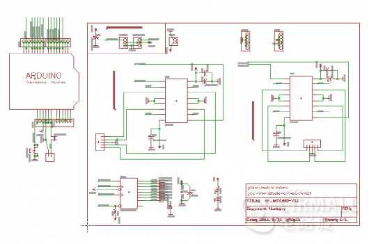
Arduino is a good introduction to electronic production. With the motor expansion board, it can be a good robot development platform. Here is a full-featured motor expansion board that can drive various simple to slightly complex projects. This is a commonly used DC motor driver module, using L293D chip small current DC motor driver chip. The pins are made Arduino compatible, which also facilitates rapid Arduino-based development by enthusiasts.
L293D motor driver board overview:
The motor driver board has many functions, is easy to operate, and has powerful driver library support and function updates. It is suitable for Arduino beginners, Arduino experimental equipment platform, Arduino interactive electronics, Arduino robots, etc. It can drive 4-way DC motors or 2-way stepper motors and also drive 2-way servos, support the latest Arduino UNO, Arduino Mega 2560
The specific features are as follows:
1.2 5V servo motor (servo) ports are connected to Arduino's high-resolution and high-precision timer - no jitter!
2. Up to 4 bidirectional DC motors and 4 PWM speed regulation (about 0.5% resolution)
3. Up to 2 stepper motors are controlled forward and reverse, single/double-step control, staggered or micro-step and rotation angle control.
4.4 H-bridges: The L293D chip provides .0.6A (peak 1.2A) current per bridge and has thermal power-off protection, 4.5V to 36V.
5. The pull-down Resistor ensures that the motor remains stopped when powered on.
6. Large terminal terminal block makes wiring easier (10 - 22AWG) and power supply.
7. With Arduino reset button.
8. 2 large terminal external power terminals ensure the separation of logic and motor drive power.
9. Compatible with Mega, Diecimila, & Duemilanove.
The physical connection diagram is as shown in the screenshot:
L293D motor driver board/motor board circuit screenshot:
Screenshot of source code of L293D motor driver board:
NXP smart car dual motor MOS tube driver
Circuit introduction
Compared with the BTN79xx series driver, the mos driver has a larger output, stronger driving ability and faster response.
use device
Half-bridge driver IR2184S
mos tube IRLR7843
Boost B0512S-1W
Display 0.96 inch OLED
Isolation circuit SN74HC244PW
Features
Realize dual motor control, powerful driving force, even the most powerful B car model motor is not a problem.
There is a 0.96-inch OLED onboard, which is convenient to display parameters during debugging and saves the space of the motherboard.
There are four DIP switches and five keys, which can be used for parameter input and mode setting.
The buzzer, as the prompt flag of the program, is used for debugging.
Design experience
The driver board of the smart car has three main functional parts: boost, half-bridge or full-bridge control, and mos switch. After understanding these three parts, you can combine and design circuits at will. For example, I can use LM2577, mc34063, LMR62014, etc. for boosting, and HIP4082 for the controller, no problem. In addition, when wiring, the most important thing to pay attention to is the line width, because it is only driven by the motor, and the current passing through is relatively large, so the motor current line needs to go wide, 120 mil is not too much, you can also open the window and apply thick tin.
Attachment content screenshot:
Smart car motor drive module circuit L298N schematic diagram + PCB source file
This is a motor drive module that must be used for smart cars. The drive chip used in this module is L298n, which can control 2 DC geared motors.
The physical map of the welding diagram is as follows:
Screenshot of the schematic diagram of the motor drive circuit:
Screenshot of PCB source file:
60V 45A high-power three-phase brushless DC motor driver supporting WIFI, dedicated to robots and electric vehicles
Three-phase brushless motor driver with super power and super torque. Support WIFI, you can use WIFI to control.
The main parameters:
Input voltage 20V~60V.
Maximum current 60A
Long-term working current 30A
WIFI: 2.4G
OSOpenwrt
It can be used in electric doors, treadmills, electric curtains, battery cars, robots, lawn mowers and other fields.
A few beautiful pictures.
Recommended courses:
Zhang Fei software and hardware open source, based on STM32BLDC brushless DC motor driver video kit
http://t.elecfans.com/topic/42.html?elecfans_trackid=fsy_post
High Voltage Thick Film Resistor
High Voltage Thick Film Resistor refers to SHV cylindrical resistors (RC Series). They are suited for all high value and voltage applications. Such as High voltage power supply. X-rays equipment, High voltage multiplier, Precision divider electron microscopes, High resolution CRT displays, Automobile Electronic, .etc.
Polypropylene Film Capacitor,Power Supply Resistors,Flat Resistor,Thick-film Resistor,HV Power Resistor
XIAN STATE IMPORT & EXPORT CORP. , https://www.shvcomponents.com