Carefully correct power factor
Globally increasing management entities are demanding power factor management.
Power levels - At such power levels, power factor management becomes a regulatory issue - it has dropped to 75W and 26W for electronics and lighting equipment respectively.
The purpose of using a power factor correction circuit is to force the input current from the power supply line to resemble the supply voltage in waveform and phase regardless of the non-sinusoidal nature of the supply current.
One of the expected results of a universal power supply design (ie, those designed to accommodate AC input voltages below 100V to above 240V) is that the power management circuitry is independent of the power supply, and the designer only needs to consider those issues related to the expected load. This power management approach can generate considerable economies of scale by reducing the type of power required to serve the global customer base. Similar advantages can also be extended to supply chain, manufacturing and inventory management operations.
However, this method also brings the following undesired results: The power obtained must meet the most stringent standards in various markets. Power standards have come a long way in the past few decades, and more importantly, the number of management entities that recognize the value of this standard has also recently increased. The reason is simple: Although it remains to be verified, the inefficient use of power is the main reason for the allocation or mandatory infrastructure investment. Low power factors can have a deadly effect on grid efficiency and have attracted worldwide attention. The European Union took the lead in introducing a power factor standard, but China’s mandatory certification (CCC), the US National Environmental Protection Agency’s (EPA) Energy Star program, and Japan's JIC-C-61000-3-2 standard all indicate that power The Factor (PF) indicator is becoming a global mandatory requirement. Moreover, the higher minimum power factor is no longer limited to high-power devices, and the updated standards and specifications are applied to electronic products such as 75W or 26W power lighting devices.
Make waves
To understand how the latest trends in the electronics industry have increased people's interest in PF, we must first understand the definition of actual power and apparent power. The actual power of the circuit is defined as the average of the product of the instantaneous voltage and current during a power cycle:
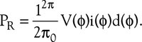 (Formula 1)
The apparent power is simply defined as the product of the root-mean-square (rms) voltage and current: ![]() (Formula 2)
(Formula 2)
PF is the ratio of PR to PA, usually expressed as a percentage: 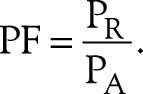 (Formula 3)
If both the voltage and current waveforms are sinusoidal and in phase, the actual power is equal to the apparent power, resulting in 100% PF. This relationship exists when the load is fully resistive, especially non-inductive heating elements and tungsten bulbs.
Reactance loads cause phase shifts between their current and the applied voltage, but because they exhibit a linear impedance, the current waveform is still a sine wave. Its PF is: ![]() (Formula 4)
(Formula 4)
The phase shift θ comes directly from the impedance:  (Equation 5)
Here, XL and RL are the reactive component and the resistive component of the net load impedance, respectively.
Alex Lidow, CEO of International Rectifier, pointed out that "about half of the electricity we use is for driving, and about 85% of them go into electromechanical or triac-driven AC induction motors. Medium (Reference 1) This common arrangement forces the grid to supply more current than is required to drive the load, thus causing troubles for meter measurement because, as Equation 1 shows, the net current includes the in-phase component and the quadrature component (fig. 1) The apparent power provided to the system is decomposed into the following two components, that is, the driving device works and extracts the actual component of the IP current and extracts the quadrature component of the motor reactive or magnetizing current IR. Thus the net current is: 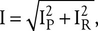 (Equation 6)
From this we can redefine the PF: 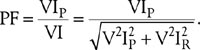 (Formula 7)


In industrial equipment, utility power companies may measure the above two powers separately, that is, using a standard kilowatt-hour meter to measure the actual component, and another kilowatt-hour meter to measure the quadrature component. In this case, billing will use the root mean square (rms) value of the two readings during the billing period. However, most utility power users only have one meter, which is quite unfair to the power company's billing: the power supplier obviously should charge in energy (or power) units, but the industry calculates the power distribution in current units. System infrastructure capacity. Assuming that the AC voltage in equation 3 has a constant amplitude and a reference phase, the constants cancel and the PF becomes (by integrating over a period of one cycle during the billing period) the ratio of the actual current to the apparent current - just as What the power company sees. In this view, the PF can measure part of the current capacity that the utility company can charge, and unfortunately, the reciprocal of the PF becomes a requirement for over-construction of the grid infrastructure. This relationship between load performance and operating costs and investment costs raises PF to the highest level defined by regulations.

Harmonic divergence
As we have seen, most of the largest and most common linear reactive loads are inductive loads, including certain types of motors, lamps, fluorescent ballasts, inductive heaters, and welders. All of these loads will cause phase delays (Figure 1). The usual power factor correction (PFC) method requires the addition of capacitors and corresponding fuse and switching devices (Figure 2). If this is all power factor management work, then you can do it. Unfortunately, in reality, the entire electronics industry presents nonlinear loads to the power grid. As a result, the increased harmonics of the basic current waveform complicate the problem. For example, a simple full-wave rectifier with a resistive load or a current-absorbing load, a capacitive filter, and the like. The filter provides the load current during most of the power line transmission period and is charged in such a time interval that the input is terminated when the input absolute value exceeds the capacitor voltage and reaches the input peak (Figure 4). Due to full-wave rectification, the periodic change of the charging current has a fundamental frequency twice the frequency of the power line. More importantly, the current waveform contains more odd harmonics, and their number and amplitude increase as the charging interval decreases. Equation 3 expands into Equation 8 by considering the harmonic components of the current waveform in the PF calculation: ![]() (Equation 8)
(Equation 8)
IH is the harmonic component of the current waveform.

The extreme case is that, as the charge interval approaches the Dirac pulse δ(t), the harmonic progression will expand indefinitely. Keep in mind that the increasing popularity of switch-mode power supplies and their ever-increasing operating frequencies has given rise to the fear that there may be a long series of large glitches in the current spectrum. The relationship between this switching behavior and power factors has motivated people to pay more attention to the evolving specification. Indeed, several major specifications promulgated around this topic, such as the European Union's EN61000-3-2 and EN60555 and their corresponding international standards IEC1000-3-2 and IEC555, all have an input current spectrum content in mains-powered equipment ( It is limited from the fundamental wave to the 40th harmonic (Reference 2).
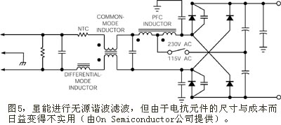
The traditional way to solve such problems in signal processing equipment is to add a low-pass filter (Figure 5). However, as the power level specified by the power factor standard decreases (which has fallen below 100W in the past few years), linear filters have become increasingly uneconomical and difficult to use.
Power IC designers have solved this problem with the same circuit topology technology that had previously exacerbated the problem at the top of the list, namely using small ICs to quickly and efficiently switch power supplies and accurately measure results. It is equally important in active PFC implementations that high-quality analog signal processing must be accomplished in the switching environment with minimal crosstalk between switching devices and linear signal processing circuitry. In addition, key indicators for PFC design include net power regulation efficiency, total harmonic distortion (THD), electromagnetic interference (EMI), power density, and raw material (BOM) costs (Reference 3).
As is common in electronic design, if you can use the signal with the required results, the problem is solved much easier (Reference 4). When pursuing PFC power adjustment, the simplification of the problem is based on seeing the input voltage waveform almost completely passing the required current waveform to the system. A PFC circuit, CRM (critical conduction mode), is a typical example of this signal processing method (Figure 6). The process is that the error amplifier compares the output (dc plus ripple) with the on-chip DC reference, and the multiplier converts the unfiltered but rectified input voltage sample according to the low-pass filtered error amplifier output, effectively providing A certain degree of output voltage regulation, and produce a current reference waveform. The control circuit controls the bypass switch and raises the inductor current to follow the reference waveform (Figure 7). The control cycle begins when the bypass switch is turned on. The sense resistor senses and scales the bypass current, where the comparator performs measurements based on the multiplier output. When the bypass current reaches the level required by the reference waveform, the comparator turns off the MOSFET. The secondary winding on the series inductor forms a current transformer and signals the detector, and the detector turns on the MOSFET when the current drops to zero.


Other PFC structures may use different control algorithms, but replace the voltage waveform with the current drawn from the power line to preserve the main target. The continuous current mode (CCM) PFC maintains an average current equal to the AC reference signal. This approach reduces the output ripple and fixes the frequency, which in turn simplifies downstream filtering, but doing so adds to the complexity of the control loop.
CRM PFC is currently used in devices that consume up to 100W. The CCM PFC is a common choice for devices with power consumption greater than 200W. In the 100W to 200W (where many consumer devices consume power in this range), power supply designers must choose circuit topologies that best fit their overall system goals. When choosing an available PFC method for your device, refer to some documents that refer to the CRM method as "transition mode" and the CCM as "average current mode (ACM)." Most power IC manufacturers that provide PFCs provide both types and often integrate with a range of related functions.
For example, the L6561 supplied by STMicroelectronics is a CRM PFC IC suitable for input from 86V to 265V. The IC provides 400V at its output and can operate with 92.8 ≤ η ≤ 97.3 and 0.89 ≤ PF ≤ 0.999 efficiency and power factor over the entire input voltage range. With only three passive components and one diode added, you can reduce the distortion of L 6561 from its original 3.7% ≤ THD ≤ 13.7% to 2.9% ≤ THD ≤ 8.1%, and it is independent of the input voltage.
The PFC IC, which costs only 30 cents (100,000 batches), draws a maximum of 90 μA at startup and draws a maximum of 5.5 mA at 70 kHz operation. Grounding the ZCD (Zero Current Detect) pin causes the IC to become inoperative and generally reduces the quiescent current to 1.4 mA. When you disconnect the ZCD pin, the internal startup timer will restart the circuit. In addition to the basic PFC functionality, the L6561 also provides overcurrent protection and resistor overvoltage protection. STMicroelectronics offers the L6561 in SO-8 or DIP-8 packages.
The NCP1601 dual-mode correction controller provided by On Semiconductor is suitable for medium power devices such as fluorescent ballasts, TV monitors and AC adapters. This IC can work with fixed frequency DCM (discontinuous conduction mode) or frequency variable CRM or a combination of both. Its architecture allows you to set the switching frequency in DCM and provide synchronization capabilities. The overvoltage and undervoltage protection thresholds are 107% and 8% of the rated output, respectively. The controller also provides resistor overcurrent protection and hysteresis thermal protection.
The 100W device circuit using the NCP1601 has an efficiency of 93% at 85V input and 96% at 265V input. In the same input voltage range, PF and THD varied from 0.995 to 0.901 and 8.3% to 38.9%, respectively. The startup, operating, and shutdown currents of the NCP1601 are 40mA, 5mA, and 50mA, respectively. On Semiconductor's NCP1601 is available in a SO-59, which sells for 59 cents (1000 shots), and a DIP-8, which sells for 72 cents (1000 shots).
International Rectifier (IR) replaced the analog multiplier and input detection circuit with a dedicated integrator chip to reduce the number of external components. The integrator operates in one clock cycle and can be quickly reset from the off state of the load or power line. The IR1150 chip uses line-voltage-dependent PWM duty cycle to avoid input detection. The control loop uses this derived reference waveform to set the average current. The chip is slightly more distorted at zero crossings near the power cycle and under light load conditions, but still meets EN61000-3-2 requirements. Unfortunately, as of this writing, the available PF, THD, and efficiency metrics have not yet been met, but they should be available when the PFC moves from its first draft to its official release.
The IR1150 provides undervoltage, overvoltage, peak current, and open circuit protection. The PFC draws a maximum of 22 mA at 1nF load and consumes 200mA in sleep mode. The IC is offered in SO-8 packages for consumer and industrial grades. The difference is in the operating temperature range. US$1.05 (10,000 in batches) consumer grade operating temperature range is 0°C to 70°C, while the US$1.38 (10,000 in batches) industrial grade products have an operating temperature range of -25°C~ +85°C. The PFC IC's operating frequency is programmable from 50 kHz to 200 kHz, and the magnetic components are smaller in size than low frequency devices.
A few semiconductor manufacturers have integrated PFC and regulators on one IC. The UCC2851x family of chips from Texas Instruments uses series PFC and PWM stages to comply with the IEC1000-3-2 standard. The PFC stage manages the leading edge modulation, while the PWM stage is responsible for the trailing edge modulation. The PFC uses an ACM control loop. Of the eight models in the series, the first four models operate PWM at a PFC clock rate, and the last four models operate at a double PFC clock rate.
As with many PFCs, the UCC2851x series offers undervoltage protection and also selects hysteresis, overvoltage protection, and peak current limiting. The controller operates at a nominal 200 kHz frequency and draws 6 mA of current. Texas Instruments is pricing the controllers with an operating temperature range of -40 °C to +105 °C as $1.80 (1000 batches) and is available in SO-20 and DIP-20 packages.
Another example of a PFC plus regulator IC is the iW2202 provided by iWatt, which announced the chip at this year's APEC (Application Power Electronics Conference). The IC manages the PFC loop in the digital domain and can operate at 90W from 90V to 264V AC and provides greater than 88.3% conversion efficiency. The iW2202-based 19.5V AC/DC adapter reference design provides less than 5% THD and a power factor greater than 0.98 over this input voltage range. The output ripple on 4.62A is on the order of 1V.
The controller, which sells for $1.29 (1000 lots), consumes less than 300 mW in standby mode. The regulator requires neither secondary feedback nor external loop compensation, which further reduces the number of external components. On-chip features include over-voltage, over-current, and over-temperature protection. The iW2202 is available in the SO-14 package.
With the recently introduced PFC, the operating frequency has been increased, which is a trend that is likely to continue and accelerate (if regulations continue to expand to new areas or new requirements for system/power interfaces). For example, it is likely that system-level sleep mode power consumption will become the focus of increasing regulations. If this is the case, the power front-end IC may be responsible for implementing the new regulations.
references:
1, Lidow, Alex, PhD, "Variable speed motion: a key to energy-savings," EOEM Design Expo, March 16, 2005, .
2, Bourgeois, JM, "Circuits for power-factor correction with regards to mains filtering," AN510/0894, STMicroelectronics, 1999.
3, "Power factor correction handbook," On Semiconductor, August 2004.
4, Black, Harold, "Stabilized Feedback Amplifiers," Bell System Technical Journal, January 1934.
Building Wire,Sheath Pvc Wire,Pvc Sheath Wire,Grounding Wire
Baosheng Science&Technology Innovation Co.,Ltd , https://www.cablebaosheng.com