Thermistor temperature sensor design and application circuit
Table 1 Types of thermistors and application of thermistor linearization improvement
Action range detection component circuit component heating component NTC PTC CTR NTC PTC CTR PTC self-heating small range thermometer thermostat small temperature difference temperature change detection heat meter thermometer temperature regulator temperature alarm device temperature switch temperature regulator the temperature of the temperature compensation circuit alarm device temperature compensation circuit - - operation at maximum temperature detection voltage or current alarm level gauge temperature detector alarm device temperature gauge switching temperature alarm level gauge intrusion prevention circuit means constant voltage circuit constant Current circuit current switch voltage switch intrusion prevention circuit memory circuit overheat prevention device negative resistance range self-heating large range anemometer flowmeter empty true liquid level gauge liquid level gauge anemometer flowmeter level gauge - - switch circuit oscillator pulse Generator constant temperature heating element thermostatic bath action delay characteristic differential temperature detector differential temperature detector differential temperature detector action delay loop breakthrough prevention circuit ultra low frequency oscillator action delay loop action delay loop breakthrough prevention circuit
Â
Table 2 Application and characteristics of thermistor:   Main use type Use purpose Resistivity temperature coefficient error structure at normal temperature Measurement of thermistor thermometer wind speed, vacuum gauge 01~10kΩ/cm 1~100kΩ/cm ±2% ±2% bead type ball type straight Thermal thermistor CTR communicator AGC time lag (TimeLag) 0.1~100kΩ/cm 0.1~100kΩ/cm ±5% ±5% 0.3~0.6φ bead type 0.3~2φ bead type hot type thermistor CTR , PTC communication machine AGC 0.1~100kΩ/cm ±5% 0.3~0.4φ Bead type small rod temperature compensation thermistor PTC transistor measurement temperature compensation 1~100Ω/cm 0.1~100kΩ/cm ±5% ±10 % Bead ball type and disc type bead ball type and disc type driver thermistor CTR relay operation delay breakthrough to prevent 1~1000Ω/cm ±5% 10φ or more disc type or bead type temperature protection CTR PTC fire Alarm overheat protection 1~100kΩ/cm 1~1000Ω/cm ±10% 0.6~2φ Bead type 5~20φ Disc type heater PTC thermostat 10~1000Ω/cm ±20% disc type PTC for main current limiting Color degaussing current prevents 1~1000Ω/cm ±20% disc type
Â
Â
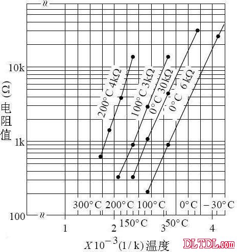
Figure 2-2 Resistance-temperature characteristics of the thermistor
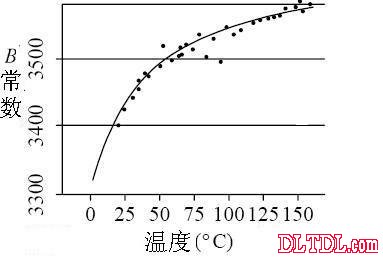
Figure 2-3 Temperature characteristics of the thermistor B constant
Thermistor's heat dissipation constant: type heat dissipation constant: K (mWC / °C) time constant (63.2%) (sec) load maximum power consumption (mW) maximum use temperature (°C) mark name air water in the air water MB beads Type 0.3~0.5 0.6~1.0 1.5~5 0.05~0.1 0.2 300 SSB Bead Type 0.8~1.3 1.5~2.5 3~7 0.1~0.2 0.5 350 SB Bead Type 1.0~1.5 2.0~3.0 5~10 0.1~0.2 0.5 350 Lφ3 glass tube type 1.0~1.5 2.5~3.5 10~15 0.2~0.3 0.5 350 Lφ6 glass tube type 1.0~1.5 2.5~3.5 10~15 0.2~0.3 0.5 350
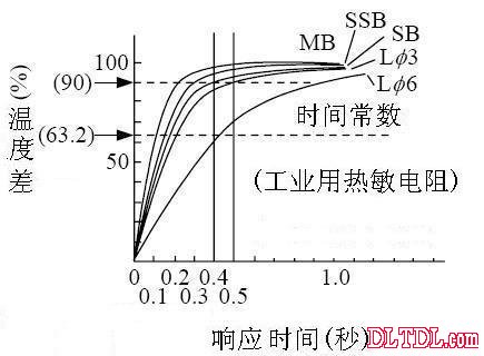
Figure 2-4 Thermal response curve of the thermistor (stirred water)
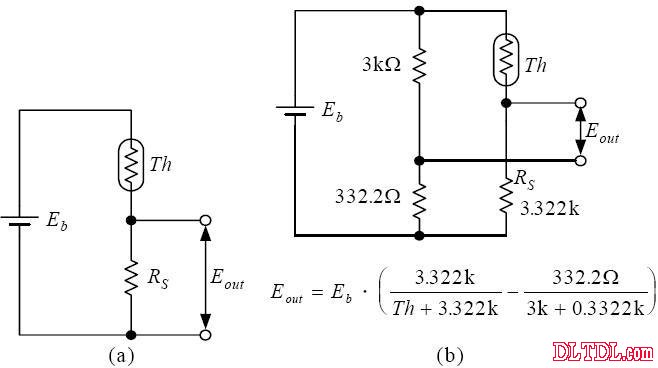
Figure 2-5 Basic wiring circuit of the thermistor bridge
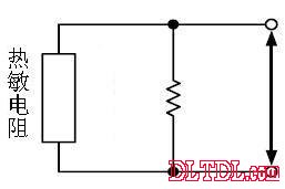
Improve the linearity of temperature-resistance characteristics
(a) One resistor in parallel, component interchangeable
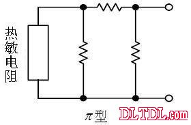
(b) Synthetic resistance type (JIS)
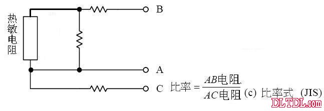
Figure 2-6 Linearity of the temperature characteristics of the thermistor
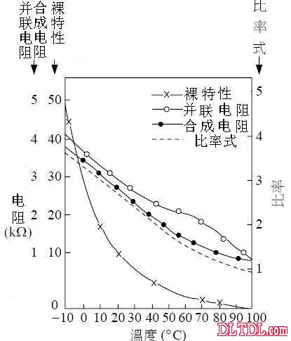
Figure 2-7 Linearity improvement of various wiring methods (bare characteristics are only the characteristics of the thermistor)
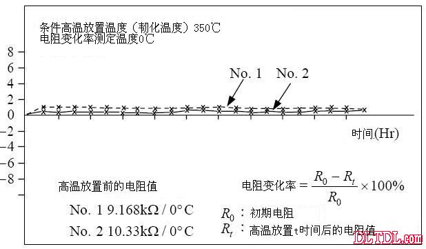
Figure 2-8 Recording characteristics of long-term changes in thermistor
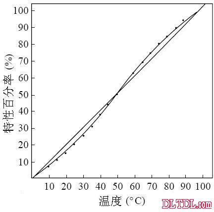
Figure 2-9 Temperature output characteristic curve
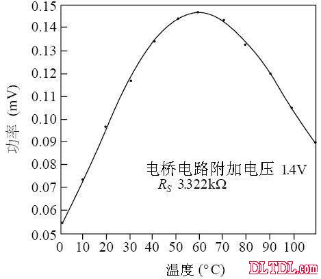
Figure 2-10 Temperature - Self Heating Power Characteristics
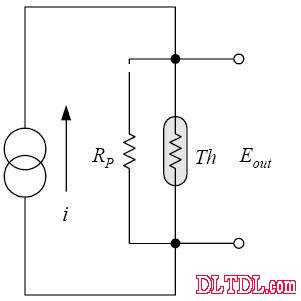
Figure 2-11 Constant current detection method (the number added after Th indicates each temperature value)
This value is used in the range of 0100 ° ° C using the TAKARA thermistor THR B, and the thermistor component is 15 KΩ at °C.
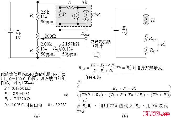
Figure 2-12 Synthetic resistance connection
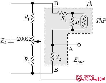
Figure 2-13 Ratio connection
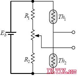
Figure 2-14 Structure of the temperature difference bridge circuit

Figure 2-15 Temperature and sensitivity changes of the thermistor
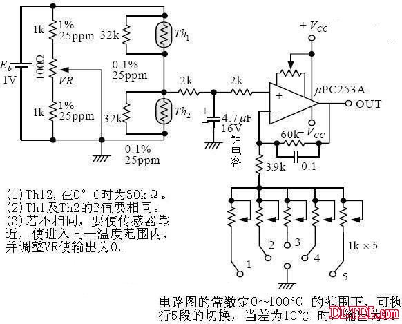
Figure 2-16 Measuring circuit for temperature difference
Temperature difference measurement loop: Range temperature (°C) Magnification error (%) 1 0~20 15.31 ±0.5°C 2 20~40 13.94 ±0.1°C 3 40~60 13.84 ±0.2°C 4 60~80 14.67 ±0.3°C 5 80~100 15.96 ±0.3°C
Error refers to sensitivity error (when measuring ±10 °C difference)
Table 5 Temperature difference output: (Figure 2-14 Bridge circuit mode): Temperature °C thermistor kΩ output (V) 5 °C temperature difference output (V) 0 30.000 0.44547100 -0.05452870 5 24.100 0.44712100 -0.05287910 10 19.490 0.44850000 - 0.05149970 15 15.850 0.45003500 -0.04996530 20 12.970 0.45135400 -0.04864640 25 10.670 0.45276400 -0.04723560 30 8.828 0.45408500 -0.04591550 35 7.343 0.45538800 -0.04461170 40 6.140 0.45658900 -0.04341100 45 5.159 0.45780300 -0.04219660 50 4.356 0.45901600 -0.04098360
Trolley Speaker,Bluetooth Trolley Speaker,Portable Speaker Trolley,Trolly Speaker With Mic
GUANGZHOU SOWANGNY ELECTRONIC CO.,LTD , https://www.jerry-power.com