RS485 design selection and application interface circuit
As an electronic engineer, the basic and widely used RS-485 serial port interface is a compulsory course, but it is also a place where people often encounter problems in their daily design. In practical applications, how to solve the RS-485 circuit design problem quickly and effectively?
RS-485 standard
The RS-485 standard is called the TIAA/EIA-485 serial communication standard. Data communication uses differential line number transmission, also known as balanced transmission. Using a pair of twisted pairs, one of the lines is defined as A and the other line is defined as B, as shown below:
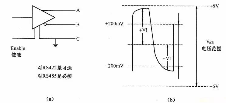
Normally, the positive level between the transmit drivers A and B is +2 to +6V, which is a logic state, and the negative level is -2 to 6V, which is another logic state. There is also a signal ground C, which has an "enable" end in RS-485, which is available and not available in RS-422. The "Enable" terminal is used to control the disconnection and connection of the transmit driver and the transmission line. When the "enable" terminal is active, the transmit driver is in a high-impedance state, referred to as the "third state", ie it is the third state distinct from the logic "1" and "0".
The receiver is also configured to be opposite to the transmitting end. The receiving and transmitting ends are connected to AA and BB through a balanced twisted pair. When there is a level greater than +200 mV between the receiving ends AB, the positive logic level is output, which is less than -200 mV. When, a negative logic level is output. The level of the receiver receiving balance line is usually between 200mV and 6V.
RS-485 considerations
1, RS485 network installation
The RS485 network topology generally adopts a terminal-matched bus type structure and does not support a ring or star network. The main purpose is to reduce the reflected signal (especially at the node and the discontinuity of the bus impedance) without affecting the signal quality.
2, RS485 terminal matching
For RS-422 and RS-485 bus networks, termination resistors are generally used for matching. However, terminal matching can be avoided at short distances and low speeds.
Generally, the terminal matching adopts the terminating resistor method, and the terminating resistor is generally 120 Ω in the RS-485 network. A resistor equivalent to the characteristic impedance of a cable. This matching method is simple and effective, but the matching resistor consumes a large amount of power, and is not suitable for a system with strict power consumption restrictions.
Another way to compare power savings is RC matching. Using a capacitor C to block the DC component can save most of the power. However, the value of capacitor C is a difficult point, and a compromise between power consumption and matching quality is required.
There is also a matching method using a diode. Although this scheme does not achieve a true "match", it uses the clamping action of the diode to quickly weaken the reflected signal and achieve the purpose of improving the signal quality. The energy saving effect is remarkable.

3, RS-485 grounding problem
The grounding of the electronic system is very important. The grounding of the RS-485 transmission network is also very important. Because the grounding system is unreasonable, it will affect the stability of the whole network. There are two major hidden dangers: common mode interference and EMI.
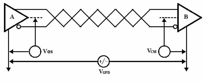
Common mode interference: RS-485 interface adopts differential transmission mode and the transceiver has a certain common mode voltage range. For example, the common mode voltage range of RS-485 transceiver is -7~+12V. Only when the above conditions are met, the entire network can normal work. As shown in the figure below, common mode interference due to ground potential difference:
Electromagnetic Radiation (EMI) Problem: The common mode portion of the driver output signal requires a return path. If there is no low-resistance return channel (signal ground), it will return to the source in the form of radiation, and the entire bus will radiate electromagnetic waves like a huge antenna.
Responses:
If the internal resistance of the interference source is not very small, consider adding a current limiting resistor on the ground line to limit the interference current.
Use floating technology to isolate the ground loop.
Use an isolated interface.
4, RS-485 transient protection
The aforementioned grounding measures only protect against low frequency common mode interference. For high-frequency transient interference, there is nothing that can be done. Because of the effect of the lead inductance, the grounding line is actually equivalent to an open circuit for high-frequency transient interference. Such transient interference can have hundreds of thousands of volts. But the duration is very short. The interface will be damaged if not properly protected. This transient interference can be protected by isolation or bypass.
Overall solution
The above are the main considerations in the design of RS485, but there are many uncontrollable factors in the actual design. In order to help engineers avoid these troubles in design, Guangzhou Zhiyuan Electronics has launched RS485 isolation transceiver module with integrated isolation, power supply and bus protection since 2003. It has launched a series of isolated RS-485 transceivers, such as RSM485CHT. RSM3485CT, RSM485ECHT, RSM485E and other products, the application of isolated RSM485 products, in addition to eliminating the potential difference of the ground loop, effectively resisting common mode interference, but also effectively protect the circuit of the MCU end in a strong interference environment, greatly reducing the interference and damage Probability and help users reduce overall design risk and procurement costs with modular design, reliable application and competitive pricing.
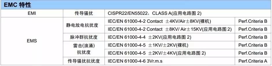
RSM series isolated RS-485 transceiver, RoHS compliant, conduction, radiation in accordance with EN55022 limit, ESD contact discharge 4KV, air discharge 8KV, EFT signal port 4KV, power port surge test 1KV, signal port 2KV.
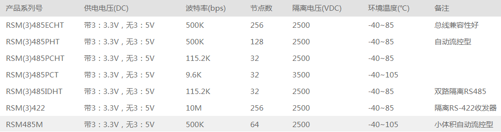
1, model list
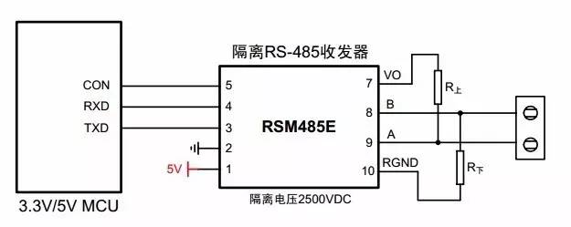
2, typical connection circuit
3, EMC characteristic test
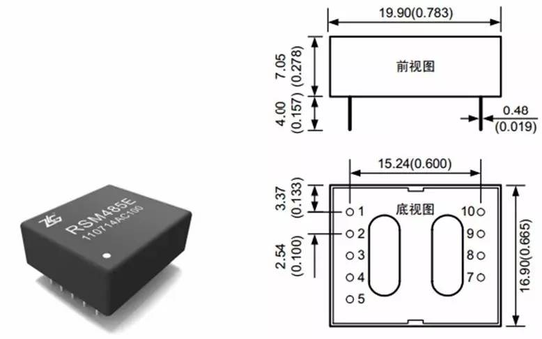
4, module physical map and size
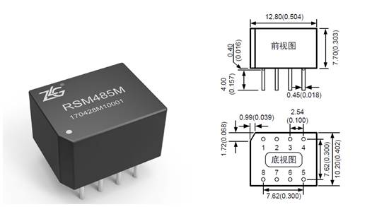
5, ultra small size model RSM485M
For applications where PCB space is limited or where the final product has stringent volume requirements, we can also choose the small size model RSM485M. RSM485M only has 1/3 of the volume of the conventional model, supports up to 64 nodes, and has a baud rate of 500kbps. It can be described as a "small steel gun" in the RS-485 isolation module.
Reading Glasses,Adjustable Reading Glasses,Stylish Reading Glasses,Rimless Reading Glasses
Danyang Hengshi Optical Glasses Co., Ltd. , https://www.hengshi-optical.com