Detailed explanation of the four schemes of the single-chip button design
In the single-chip system, the buttons are common input devices. In this article, Jiang introduces several key hardware and software design skills. Generally, there are generally four options for the design of the buttons: one is to directly detect a single button on the GPIO port, as shown in Figure 1.1; the other is to use a matrix keyboard for more buttons, as shown in Figure 1.2; To the external interrupt pin, use the edge signal generated by the button press to perform button detection, as shown in Figure 1.3; Fourth, using the ADC of the microcontroller, after the different buttons are pressed, the voltage on the ADC interface can be made different, according to The difference in voltage allows the button to be recognized, as shown in Figure 1.4.
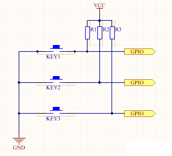
Figure 1.1 Scheme 1
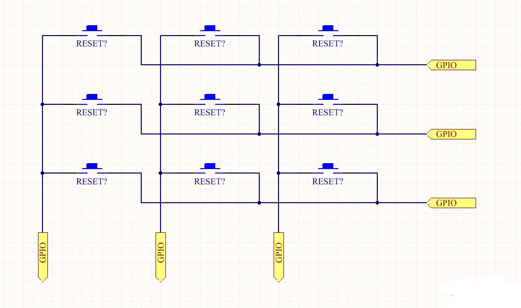
Figure 1.2 Scheme 2
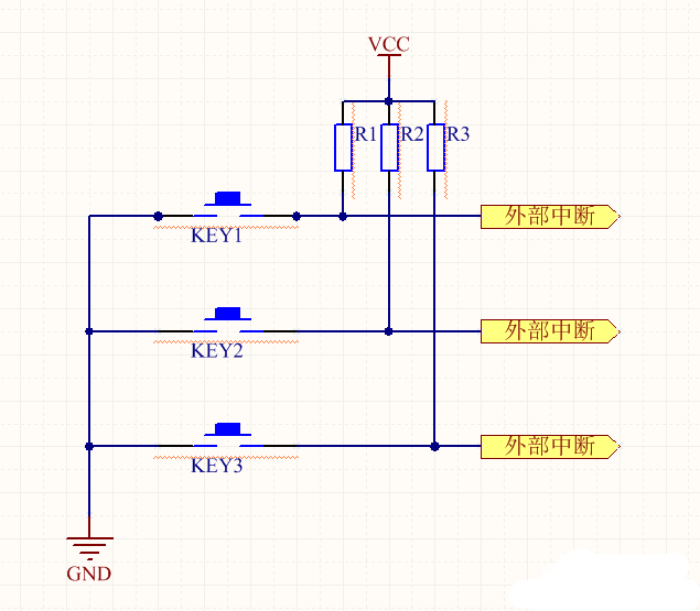
Figure 1.3 Scheme 3
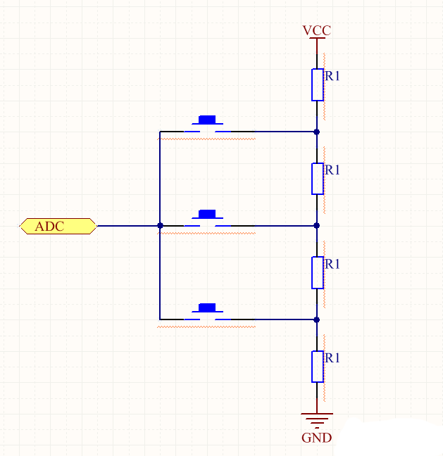
Figure 1.4 Scheme 4
In the above four designs, each has its own advantages and disadvantages. The first one is the simplest and most basic. It is easy to understand and use for beginners of single-chip microcomputers, but the disadvantage is that it is necessary to continuously detect whether the keys are pressed in the main loop and to perform debounce processing. If a function task in the main loop takes a long time, the button will have different degrees of "failure". Second, the advantage is the ability to expand as many buttons as possible with limited GPIO. However, the disadvantages are the same as above, and it is necessary to continuously detect whether the button is pressed. The third way is the highest efficiency, no need to cycle detection button is pressed, but the disadvantage is that the microcontroller needs to have enough external interrupt interface for use; the fourth advantage is that only one ADC interface of the microcontroller, one The line can identify multiple buttons. The disadvantage is that if the button is not properly connected internally, the button may be in series and the jitter generated by the button may cause a certain recognition error.
Based on the above three common button designs, I now share the button schemes I have summarized in my study and work.
Improvement one: On the basis of the original scheme 1, adding the AND circuit, so that any one button is pressed, an interrupt can be generated, and then it is recognized in the interrupt which button is pressed. Therefore, no cyclic scanning is required, which greatly improves the efficiency. The scheme is shown in Figure 1.5. It is only necessary to add a diode corresponding to each button. By using the line and characteristics of the diode, it is possible to generate an interrupt signal by pressing any button, but the buttons do not affect each other. The diode can be selected from ordinary rectifier diodes.
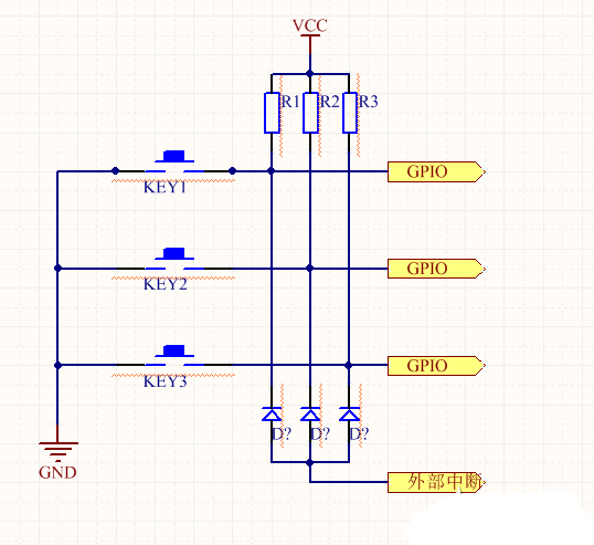
Figure 1.5 Improvement 1
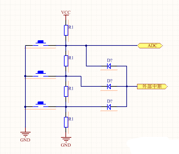
Figure 1.6 Improvement 2
Improvement 2: On the basis of the original ADC button, the diode can be added to realize the key interrupt, and the AD conversion is performed in the interrupt service program to identify the button. The circuit is shown in Figure 1.6.
Improvement 3: Because the buttons are inevitably jittery, the button debounce can be degaussed by hardware and software. Now share a very simple and effective hardware acne method: connect a 104 or so capacitor in parallel with the button. The software basically does not need to be processed to avoid jitter.
Improvement 4: Under the scheme of button scan detection, if a function in the main loop takes a long time, the button will have a long or short “failureâ€, and now share one of my solutions. Put the key scan into the timer interrupt, so that the button press can be detected periodically without being affected by the main loop. Moreover, the different states of the buttons can be resolved, that is, pressed, held, bounced, and pressed to achieve a richer function. However, it is necessary to pay attention to two points. First, the timer's timing time cannot be too long or too short. If it is too long, it will not be detected. If it is too short, it will take a lot of time resources. Second, the interrupt service program needs to be simple and clear, only for detection, through the global variable transfer, complete the key response in the main loop, try not to take too much time in the interrupt service function.
Spring Clamp Terminal Block,Screwless Spring Terminal Blocks,Spring Conductor Terminal,Spring Clip Terminal Blocks
Wonke Electric CO.,Ltd. , https://www.wkdq-electric.com