Detailed installation requirements and methods for several common flow meters
The flowmeter is an indispensable instrument for measuring the flow of liquid and gas. Everyone must have seen many different types of flowmeters. The correct installation method is very important for the flowmeter. Today, Xiaobian introduces the installation requirements of several common flowmeters.
01 electromagnetic flowmeter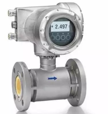
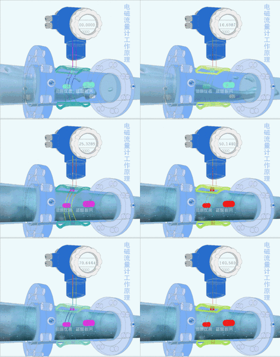
First introduced is the electromagnetic flowmeter, readers who are instrumentalists must have seen electromagnetic flowmeters on many occasions.
The measurement principle of the electromagnetic flowmeter does not depend on the characteristics of the flow. If there is a certain turbulence and vortex generated in the pipeline in the non-measurement zone, it is independent of the measurement.
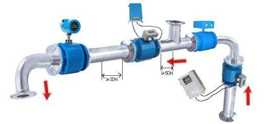
A. There should be no large vibration source at the installation site, and reinforcement measures should be taken to stabilize the pipeline near the instrument;
B. It cannot be installed near large transformers, motors, pumps, etc., which generate large magnetic fields to avoid interference from electromagnetic fields.
C. When connecting the sensor to the pipeline, ensure full pipe operation, preferably vertical installation;
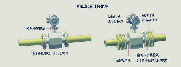
D. The transmitter casing, shielded cable, measuring body and the pipes at both ends should be grounded. The grounding pole should be set separately. The grounding resistance should be less than 10 ohms and cannot be connected to the electrical or public grounding network.
E. It is required to have a straight pipe section with 3 times the diameter of the pipe after 5 times.
Detailed explanation is as follows
If there is a steady-state eddy current in the measurement zone, it will affect the stability of the measurement and the accuracy of the measurement. In this case, the length of the straight pipe section can be increased, a flow stabilizer can be used or the cross section of the measurement point can be reduced to stabilize the flow velocity distribution.
The flow meter can be installed horizontally and vertically, but it should be ensured that the influence of deposits and bubbles on the measuring electrode is avoided and the axial direction of the electrode is kept good. When installed vertically, the fluid should flow from bottom to top.
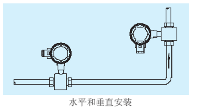
The sensor cannot be installed in the highest position of the pipe, which is easy to accumulate air bubbles.
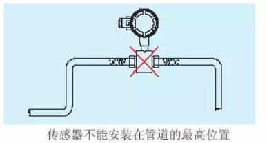
Make sure that the flow sensor is full of the fluid under test when measuring, and that the non-full tube state cannot occur.
If the pipe is not full or the outlet is vented, the sensor should be mounted on a siphon.

The conventional straight pipe section of the electromagnetic flowmeter is required to be 5D after the first 10D, and there are different requirements in the case of the bent pipe and the valve.
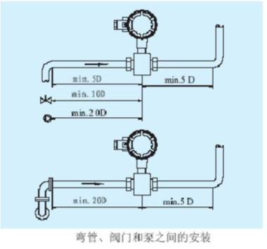
Reasons why the electromagnetic flowmeter is grounded:
The measuring electrode in the electromagnetic flowmeter is in a DC or AC electric field. If its environment cannot be effectively shielded under a non-interfering condition, it will seriously interfere with the measurement.
Whether the sensor case is grounded or not is directly related to the accuracy and stability of the measurement. The grounding wire must not transmit any interference voltage. Therefore, the electromagnetic flowmeter requires a very reliable grounding. The grounding shielding should be done, otherwise the interference current will be generated.
However, the benefits of electromagnetic flowmeter grounding: If the pipe connecting the sewage flow meter is (relative to the measured medium), the grounding ring should be used, and its material should be selected according to the corrosiveness of the measured medium.
In the case of a Teflon sensor, in order to protect the flanging of the Teflon from damage, a grounding ring is required.
Ultrasonic flowmeter is also a common flowmeter. Its installation is the easiest and most convenient to install all flowmeters. Just select a suitable measuring point, input the pipeline parameters at the measuring point into the flowmeter, and then put the probe. It can be fixed on the pipe.
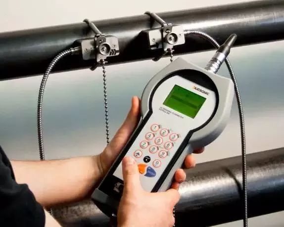
The installation of ultrasonic flowmeter mainly follows the following three points:
1. Select a fluid-filled material that is evenly dense and easily ultrasonically transmitted, such as a vertical pipe section or a horizontal pipe section.
2. The installation distance should be more than 10 times straight pipe diameter upstream, 5 times straight pipe diameter downstream, no straight pipe section with any valve, elbow, variable diameter, etc. The installation point should be far away from valves, pumps, high voltage and Interference sources such as inverters.
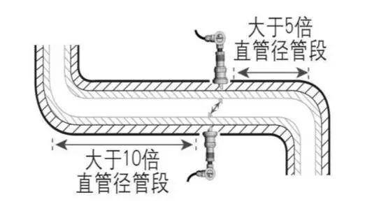
3. Avoid installation at the highest point of the piping system or vertical piping with free exits.
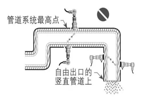
4. For open or half full pipe, the flowmeter should be installed at the U-shaped pipe section.
03 vortex flowmeter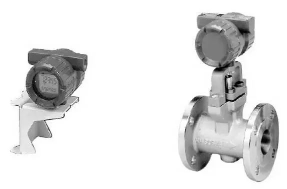
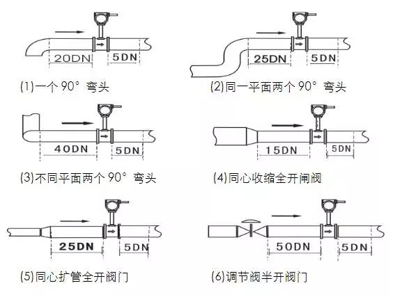
The main installation requirements for vortex flowmeters are for straight pipe sections. The upstream and downstream sides of the vortex flowmeter should have a long straight section.
For vortex flowmeters, when measuring gas flow, if the gas to be measured contains a small amount of liquid, the flowmeter should be installed at a higher point in the pipeline.
When measuring liquid, if the liquid to be tested contains a small amount of gas, the flow meter should be installed at the lower part of the pipeline.
04 turbine flow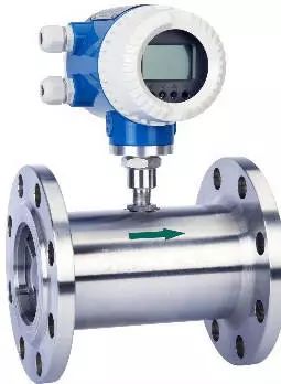
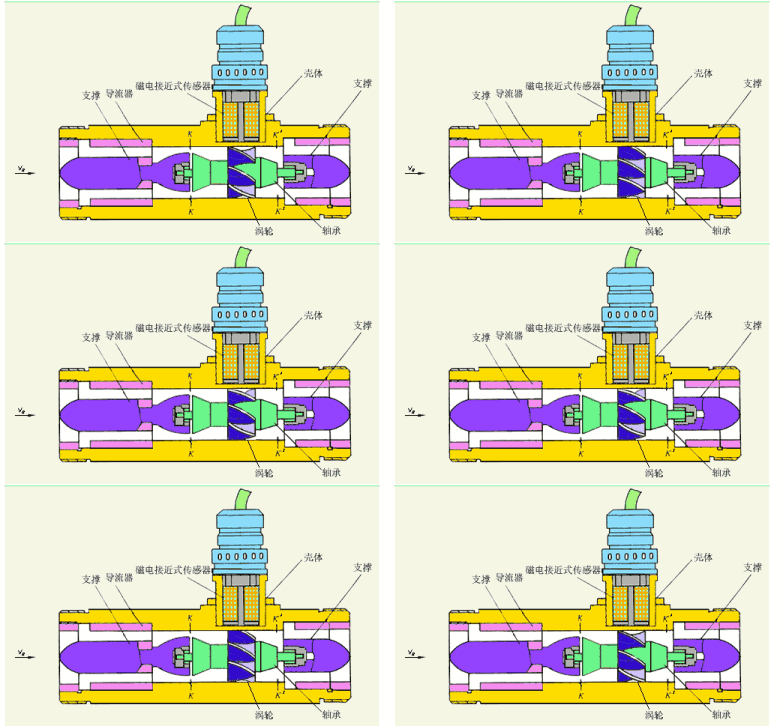
When installing the turbine flowmeter, it should be kept away from the external electric field and magnetic field. If necessary, effective shielding measures should be taken to avoid external interference.
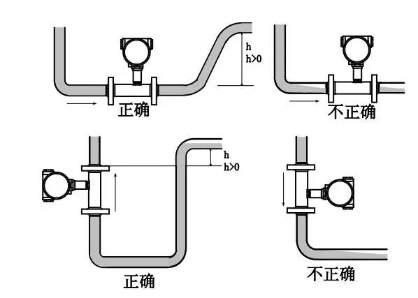
The turbine flow meter can be installed horizontally and vertically, and the fluid direction must be upward when installed vertically. The liquid should be filled with tubing and must be free of air bubbles.
When installing, the direction of liquid flow should be the same as the direction of the arrow on the sensor housing indicating the direction of flow. The pipe must be filled with fluid in order to ensure accurate measurement.
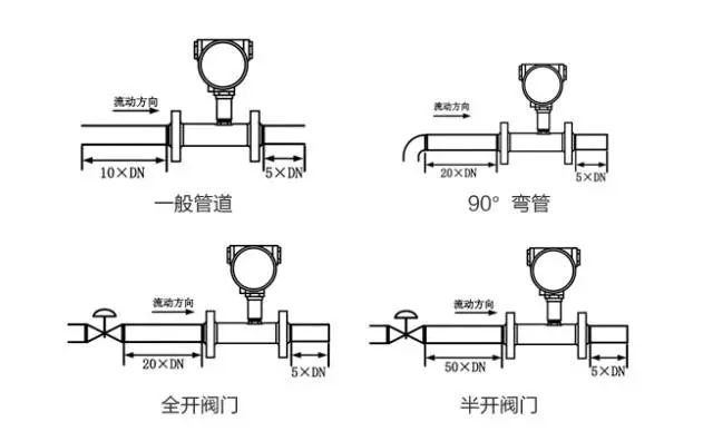
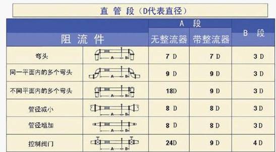
The upstream end of the flowmeter shall have at least 10 times the straight pipe length of the nominal diameter, and the downstream end shall be not less than 5 times the straight pipe section of the nominal diameter. The inner wall shall be smooth and clean, free from defects such as dents, scale and skin.
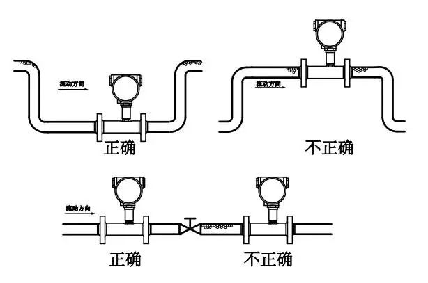
The axis of the pipe of the sensor should be aligned with the axis of the adjacent pipe, and the gasket for connecting the seal must not penetrate into the inner cavity of the pipe. Straight pipe sections in different situations are required as shown below.
At the same time, it should avoid the generation of air bubbles in the pipeline during installation, otherwise it will affect the accuracy of measurement.
05 power bar flowmeter
The Verabar flow sensor is a flow sensor designed according to the differential pressure working principle and the plug-in mounting method.
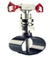
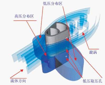
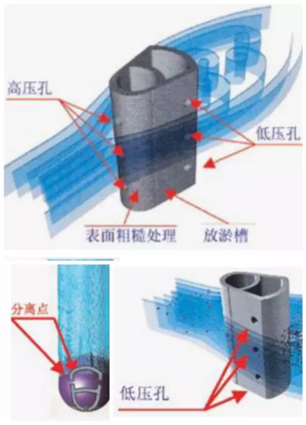
Structural features: scientific cross-sectional shape, unique anti-blocking design, rough surface treatment of the sensor and anti-sludge tank.
1. Basic installation of horizontal pipes
For horizontal pipes, it is recommended to install the gas within 160 degrees above the pipe, especially for gas with a large amount of gouache.
It is recommended to install the liquid within 160 degrees below the pipe, especially for liquids containing a large amount of gas, we only recommend this installation;
However, it is important to note that for liquids that are extremely vaporizable, such as liquid olefinic media, the direction of insertion is the same as the gas, above the pipe.
When measuring steam, we only recommend that the sensor be installed within 160 degrees of the pipe and that the sensor is at the highest point of the entire measuring device.

For vertical pipes, it can theoretically be installed within 360 degrees. For wet gases containing a lot of moisture, it is recommended to tilt the sensor up to 5 degrees when installed, as shown on the left.
For liquids containing large amounts of gas, it is recommended that the sensor be tilted down 5 degrees when installed, as shown in the image to the right. For steam, it is recommended to tilt the sensor 5 degrees when installed, as shown on the right, and the sensor should be at the highest point in the entire measurement system.

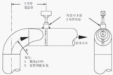
Minimum straight pipe section requirements - 2D installation after bending is shown.
When the straight pipe section on the pipeline is not long enough, we recommend installing the power bar at the inner diameter of the pipe twice after the pipe bend. Because the fluid profile after the pipe bend is complicated, the fluid coefficient K needs to be properly adjusted. After adjusting the K factor, the measurement accuracy is ±3% and the repeatability is ±0.3%.
Conclusion
Through the introduction of the above flowmeter, the installation method of the flowmeter under common working conditions has been relatively clear. For the installation of the flowmeter under complicated working conditions, specific analysis of the specific situation is needed, and accumulating rich experience is the most important part of solving the problem. .
Black modules are ideal for use in roofs, carports and photovoltaic construction (BIPV). The black roof and building façade are fashionable and beautiful, and at the same time have power generation benefits, which are especially loved by distributed users in Japan, the Middle East, and Europe and the United States.
The SUNKET All-Black Series Modules, with its true black and consistent color, can be perfectly integrated with the building (the villa effect is better), and enhance the aesthetic effect of the overall building.
The Solar Cell adopts nano-scale black silicon texturing technology, which reduces the reflectivity of the cell, improves the utilization rate of sunlight, and improves the cell efficiency and module power.
The SUNKET All-Black Series Module also integrates various technologies such as Half-cut and MBB to achieve higher power output and reliability. Using half-cut technology, reducing resistance loss and improving power output; using MBB technology can shorten the current transmission distance, reduce the internal resistance loss of the cell, and bring more power output to customers. At the same time, the half-cut technology can also reduce the hot spot temperature of the module, and the MBB technology has better anti-cracking ability, which can improve the reliability of the module and meet the needs of high safety performance of the roof.
All Black Solar Panels, Pure Black Solar Panels, Best All Black Solar Panels, 400 watt q cells Mono All-Black Solar Panel, Top Tier All Black Solar Panel
Wuxi Sunket New Energy Technology Co.,Ltd , https://www.sunketsolar.com