The article tells you how to choose the size of the resonant rod to optimize the power capacity
With the development of the industry, power and intermodulation requirements become the bottleneck of more and more products. Therefore, the power and intermodulation indicators of products are becoming the key parameters to measure the technical level of a filter design and production enterprise. This article mainly focuses on how to select the optimal size of the resonating rod under the premise of a certain single-cavity size, so that its power capacity reaches the best state.
We first analyze the distribution and strength of the electric field inside a single cavity. As we all know, the electric field in a resonant single cavity is mainly distributed between the upper surface of the resonant rod and the cover plate, the inner wall of the resonant rod and the outer surface of the tuning screw, and the electric field in other places is weak. When there is power passing through the resonant cavity, the strongest point of the electric field is the key point to limit the power capacity of the single cavity. Therefore, the key to solving the power problem is to find ways to reduce the electric field strength at the strongest point of the electric field.
Now we look for the strongest point of the electric field inside a single cavity under normal circumstances? Assuming that the size of a single cavity is a*b*c, the outer radius of the resonant rod is Rout, the inner radius is Rin, and the tuning screw radius is Rsc, then the distance between the tuning screw and the inner wall of the resonant rod is d1=Rin-Rsc, and the surface of the resonant rod is The cover distance is d2. As we all know, single-cavity resonance in the case of the electric field is mainly distributed in two areas: between the resonant rod plate and cover plate, resonance rod wall and the tuning screw, if necessary, also need to take into account the electric field between the resonant rod plate and the sidewall (When the single cavity is less frequent). Due to the “wood barrel†effect, simply increasing the power capacity of one area (that is, reducing the electric field intensity in this area) cannot increase the power capacity of a single cavity, and it is necessary to make the electric field intensity of both areas relatively small at the same time. Makes the single chamber harder to light.
First consider the electric field between the surface of the resonant rod plate and the cover plate. As can be seen in the figure, the electric field distribution between the surface of the resonant rod plate and the cover plate can be seen at a certain moment.
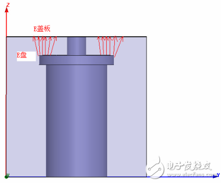
As can be seen from the figure, 1. When the frequency is low (less than 900M), the electric field on the cover plate is almost the same as the electric field on the disk surface when the resonance coil is large;
2. When the frequency is higher (above 1.8G), when the surface of the resonant rod is small, the electric field on the surface of the disk is stronger than the electric field on the surface of the lid. The multiple relationship between the two is related to the size of the disk surface of the resonant rod.
Consider the electric field between the inner wall of the resonator and the tuning screw. The figure below shows the electric field distribution of the area at a certain moment.
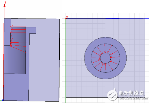
As can be seen from the figure, the power lines in the region are basically evenly distributed in the longitudinal direction, but in the horizontal direction, the distribution of the power lines is obviously not uniform. The closer to the surface of the tuning screw, the denser the power lines, that is, the stronger the electric field. At the surface of the tuning screw, the electric field is the strongest. Since the power lines on the inner wall of the resonance rod almost all stop on the surface of the tuning screw, the electric fields of the two are as follows: E inner wall (Ein)*S inner wall (Sin)=E screw(Esc)*S screw(Ssc),Esc/Ein =Sin/Ssc=2*pi*Rin/2*pi*Rsc=Rin/Rsc. That is, the ratio of the two electric fields is the reciprocal of the ratio of the two radii.
From the above analysis, it can be seen that the strongest points of the electric field in the two regions are respectively on the upper surface of the resonant rod and the surface of the tuning screw. Here we analyze the relationship between the two. When the electric fields at the strongest points of the two electric fields are equal, the two areas reach the maximum power capacity at the same time, so that the single cavity can reach the maximum power capacity. Assuming that the potential difference between the resonant rod and the cover plate is V at a certain moment, the line integral of the electric field along the surface of the resonant rod plate to the cover plate surface and the line integral along the inner surface of the resonator rod to the screw surface are equal and both are V. Consider two situations:
1. The frequency is low, and when the surface of the resonant rod is large, the electric field strength between the surface of the resonant rod and the cover plate is a constant value Eup. Then V=Eup*d2=(Esc+Ein)/2*d1, Eup*d2=( Rsc/Rin*Esc+Esc)/2*d1=Esc*(Rsc+Rin)/(2Rin)*d1 The maximum electric field in both regions is equal, then, Eup=Esc, d2=(Rsc+Rin)/(2Rin)* D1 is the equation that needs to be satisfied to maximize the single cavity power capacity under this condition.
For example, the resonance rod face is 3mm away from the cover plate, and the tuning screw diameter is 4mm. From the equation above, we can calculate the optimal value of the inner diameter.
3=(2+Rin)/(2Rin)*(Rin-2)
Obtain Rin = 6.6mm (about), that is, the optimal value of the inner diameter of the resonant rod is 13.2mm.
Note: The above equations all require that the resonant frequency of the single cavity be satisfied.
2. The frequency is relatively high and the surface of the resonant rod is small. At this time, the electric field strength between the surface of the resonant rod and the cover is not constant. Assuming that the electric field of the resonant rod is Ecp and the electric field at the cover is Etop, we assume the average electric field of the two electric fields. The strength is Eup, then Ecpâ€Eup, and Ecp=Esc, then it needs to satisfy:
D2†(Rsc+Rin)/(2Rin)*d1
Therefore, in the above example, if the surface of the resonant rod is very small, the best value of the inner diameter of the resonant rod should be Rin slightly less than 6.6 mm.
From the above analysis we can conclude that:
1. When the frequency is low, and the resonance coil is large, we should try to find a way to increase the distance between the resonance coil plate and the cover plate. At the same time, we should try to satisfy the following equation: d2=(Rsc+Rin)/(2Rin) *d1, otherwise, the tuning screw is easy to light.
2. When the frequency is high, we should try to increase the disk of the resonant rod to make the electric field on the surface of the resonant rod as uniform as possible while satisfying d2 (Rsc+Rin)/(2Rin)*d1.
3. At the same time, we can also use the equation d2=(Rsc+Rin)/(2Rin)*d1 to analyze whether the resonant disk is to be fired first or the screw is to be fired at the limit power. D2 (Rsc+Rin)/(2Rin)*d1 is the first ignition of the screw, d2 ((Rsc+Rin)/(2Rin)*d1), then the surface of the resonance rod is sparked first.
4. If ignition has occurred, the distance between the resonance rod and the cover plate cannot be blindly increased when the power is improved, because if the inner diameter dimension of the resonance rod is not improved, the tuning screw is as easy to fire.
Aluminum Alloy Die Casting Blank
Aluminum Alloy Die Casting Blank,Pressure Die Cast,Die Casting Products Alloy,Molded Precision Die Parts Cast
Dongguan Metalwork Technology Co., LTD. , https://www.dgdiecastpro.com