Common temperature sensor analysis, principle, classification and application of temperature sensor
A temperature transducer is a sensor that senses temperature and converts it into an available output signal. The temperature sensor is the core part of the temperature measuring instrument and has a wide variety. According to the measurement method, it can be divided into two types: contact type and non-contact type. According to the characteristics of sensor materials and electronic components, it can be divided into two types: thermal resistance and thermocouple.
Contact type
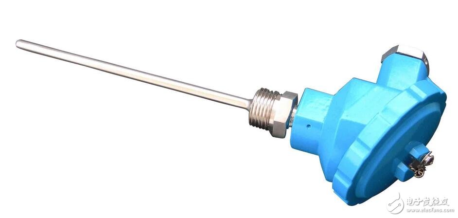
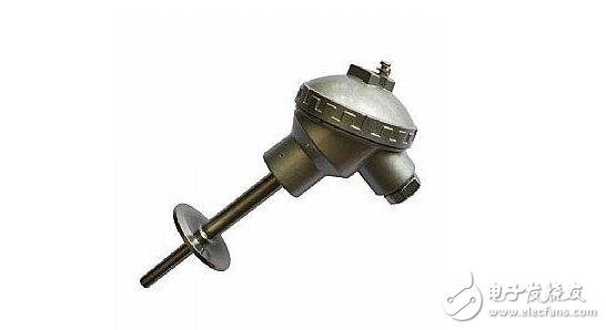
The detection part of the contact temperature sensor has good contact with the object to be tested, which is also called a thermometer.
The thermometer achieves thermal equilibrium by conduction or convection, so that the indication of the thermometer can directly indicate the temperature of the object to be measured. Generally, the measurement accuracy is high. The thermometer also measures the temperature distribution inside the object within a certain temperature range. However, for moving objects, small targets, or objects with small heat capacity, large measurement errors are generated. Commonly used thermometers include bimetal thermometers, glass liquid thermometers, pressure thermometers, resistance thermometers, thermistors, and thermocouples. They are widely used in industries, agriculture, commerce and other sectors. These thermometers are often used in everyday life.
With the wide application of cryogenic technology in defense engineering, space technology, metallurgy, electronics, food, medicine, and petrochemical industries, and the study of superconducting technology, low temperature thermometers measuring temperatures below 120K have been developed, such as cryogenic gas thermometers and steam. Pressure thermometer, acoustic thermometer, paramagnetic salt thermometer, quantum thermometer, low temperature thermal resistance and low temperature thermocouple. The cryogenic thermometer requires the temperature sensing element to be small in size, high in accuracy, reproducible and stable. Carburized glass thermal resistance formed by carburizing and sintering of porous high silica glass is a temperature sensing element of a low temperature thermometer, which can be used to measure the temperature in the range of 1.6 to 300K.
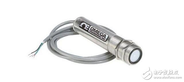
Contactless
Its sensitive components are not in contact with the measured object, also known as non-contact temperature measuring instrument. This meter can be used to measure the surface temperature of moving objects, small targets and small heat or rapid temperature (transient) objects, as well as the temperature distribution of temperature fields.
The most commonly used non-contact temperature measuring instrument is based on the basic law of black body radiation, called the radiation temperature measuring instrument. Radiation thermometry includes brightness methods (see optical pyrometers), radiation methods (see radiant pyrometers), and colorimetric methods (see colorimetric thermometers). All types of radiation temperature measurement methods can only measure the corresponding photometric temperature, radiation temperature or colorimetric temperature. Only the temperature measured for a black body (an object that absorbs all radiation and does not reflect light) is the true temperature. To determine the true temperature of an object, the surface emissivity of the material must be corrected. The surface emissivity of the material depends not only on the temperature and wavelength, but also on the surface state, the coating film and the microstructure, so it is difficult to measure accurately. In automated production, it is often necessary to use radiation temperature measurement to measure or control the surface temperature of certain objects, such as steel strip rolling temperature, roll temperature, forging temperature and temperature of various molten metals in a smelting furnace or crucible. . In these specific cases, the measurement of the surface emissivity of an object is quite difficult.
For automatic measurement and control of solid surface temperatures, additional mirrors can be used to form a blackbody cavity with the surface being measured. The effect of additional radiation can increase the effective radiation and effective emission coefficient of the surface being measured. By using the effective emission coefficient, the measured temperature is corrected by the meter, and finally the true temperature of the measured surface can be obtained. The most typical additional mirror is a hemispherical mirror. The diffuse radiant energy of the surface to be measured near the center of the ball is reflected back to the surface by the hemispherical mirror to form additional radiation, thereby increasing ε as the surface emissivity of the material and Ï as the reflectivity of the mirror. As for the measurement of the true temperature of the gas and liquid medium, a method of inserting a tube of heat resistant material to a certain depth to form a black body cavity can be used. The effective emission coefficient of the cylindrical cavity after the heat balance with the medium is obtained by calculation. In the automatic measurement and control, this value can be used to correct the measured bottom temperature (ie, the medium temperature) to obtain the true temperature of the medium.
Advantages of non-contact temperature measurement: The upper limit of measurement is not limited by the temperature resistance of the temperature sensing element, so there is no limit in principle for the highest measurable temperature. For high temperatures above 1800 °C, non-contact temperature measurement methods are mainly used. With the development of infrared technology, the radiation temperature measurement gradually spreads from visible light to infrared light, and has been adopted below 700 ° C until normal temperature, and the resolution is high.
Temperature measurement applications are very extensive. Not only do the production processes require temperature control, but some electronic products also need to measure their own temperature. For example, the computer should monitor the temperature of the CPU, the motor controller should know the temperature of the power drive IC, etc. A commonly used temperature sensor.
Temperature is a parameter that often needs to be tested in practical applications. From steel manufacturing to semiconductor production, many processes rely on temperature. Temperature sensors are the bridge between the application system and the real world. This article provides a brief overview of the different temperature sensors and describes the interface to the circuit system.
Common temperature sensor principle and applicationThermistor
There are many types of sensors used to measure temperature, and thermistors are one of them. Many thermistors have a negative temperature coefficient (NTC), which means that their resistance increases as the temperature drops. In all passive temperature sensors, the sensitivity of the thermistor (ie, the change in resistance for each degree of temperature change) is highest, but the resistance/temperature curve of the thermistor is non-linear.
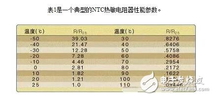
These data are measured on a Vishay-Dale thermistor, but it also represents the overall condition of the NTC thermistor. Wherein the resistance value is given as a ratio (R/R25), which represents the ratio of the resistance at the current temperature to the resistance at 25 °C. Usually the same series of thermistors have similar characteristics and the same resistance / Temperature curve. Taking the thermistor series in Table 1 as an example, a resistance of 10KΩ at 25°C is 28.1KΩ at 0°C and 4.086KΩ at 60°C; similarly, the resistance is 5KΩ at 25°C. The thermistor has a resistance of 14.050 KΩ at 0 °C.
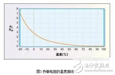
It can be seen from the figure that the resistance/temperature curve is non-linear.
Although the thermistor data here is in increments of 10 ° C, some thermistors can be in increments of 5 ° C or even 1 ° C. If you want to know the resistance at a certain temperature between two points, you can use this curve to estimate, you can also directly calculate the resistance value, the formula is as follows:
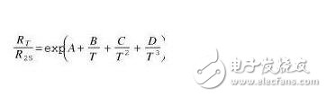
Here T refers to the absolute temperature of Kelvin, and A, B, C, and D are constants, which vary according to the characteristics of the thermistor. These parameters are provided by the manufacturer of the thermistor.
Thermistors generally have an error range that is used to specify the consistency between the samples. The error value is usually between 1% and 10% depending on the material used. Some thermistors are designed to be interchangeable for applications where field adjustment is not possible. For example, an instrument, user or field engineer can only replace the thermistor and cannot be calibrated. This thermistor is more accurate than normal. It is much higher and much more expensive.
Figure 2 is a typical circuit for measuring temperature using a thermistor. Resistor R1 pulls the thermistor's voltage up to the reference voltage, which is generally consistent with the ADC's reference voltage, so if the ADC's reference voltage is 5V, Vref will also be 5V. The thermistor and the resistor are connected in series to generate a partial voltage, and the resistance change causes the voltage at the node to also change. The accuracy of the circuit depends on the error of the thermistor and the resistor and the accuracy of the reference voltage.
Self-heating problem
Since the thermistor is a resistor, a certain amount of heat is generated when current flows through it, so the circuit designer should ensure that the pull-up resistor is large enough to prevent the thermistor from self-heating, otherwise the system measures the temperature generated by the thermistor. Heat, not the temperature of the surrounding environment.
The effect of the energy consumed by the thermistor on temperature is expressed in terms of the dissipation constant, which is the number of milliwatts required to increase the thermistor temperature by 1 °C above ambient temperature. The dissipation constant is different depending on the thermistor package, pin specifications, encapsulation material, and other factors.
The allowable self-heating and current limiting resistors of the system are determined by the measurement accuracy. The measurement system with a measurement accuracy of ±5 °C has a specific accuracy of ±1 °C. The thermistor that the measurement system can withstand is self-heating.
It should be noted that the resistance of the pull-up resistor must be calculated to limit the self-heating power consumption over the entire measured temperature range. After the resistance value is given, the dissipated power also varies at different temperatures due to the change in the thermistor resistance.
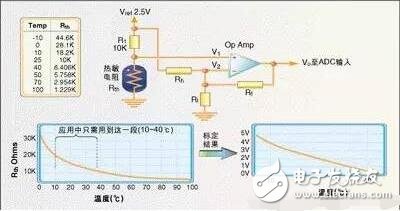
Sometimes the input of the thermistor needs to be calibrated to get the proper temperature resolution. Figure 3 is a circuit that extends the temperature range of 10 to 40 °C to the entire 0 to 5 V input range of the ADC.
The operational amplifier output formula is as follows:
Once the input of the thermistor is calibrated, the actual resistance to temperature can be graphically represented. Since the thermistor is non-linear, it needs to be represented by a graph. The system needs to know the value of the ADC corresponding to each temperature. The accuracy of the table is specifically in 1 ° C increments or 5 ° C increments depending on the specific application. set.
Cumulative error
When measuring temperature with a thermistor, select the sensor and other components in the input circuit to match the required accuracy. In some cases, a resistor with a precision of 1% is required, and some may require a resistor with a precision of 0.1%. In any case, a table is used to calculate the effect of the cumulative error of all components on the measurement accuracy, including the resistor, the reference voltage, and the thermistor itself.
If you want high precision and want to spend less, you need to calibrate the system after it is built. Since the board and the thermistor must be replaced in the field, it is generally not recommended. In the case that the device cannot be replaced in the field or the engineer has other methods to monitor the temperature, the software can also create a table of temperature corresponding to the ADC change. In this case, other tools are needed to measure the actual temperature value, and the software can create a corresponding table. For some systems where the thermistor must be replaced in the field, the component to be replaced (sensor or the entire analog front end) can be calibrated at the factory and saved on the disk or other storage media. Of course, the component replacement software It must be possible to know the use of the calibrated data.
In general, the thermistor is a low-cost temperature measurement method, and it is also very simple to use. Below we introduce the resistance temperature detector and the thermocouple temperature sensor.
Resistance temperature detector
A resistance temperature detector (RTD) is actually a special wire whose resistance varies with temperature. Usually RTD materials include copper, platinum, nickel, and nickel/iron alloys. The RTD element can be a wire or a thin film coated on a ceramic substrate by electroplating or sputtering.
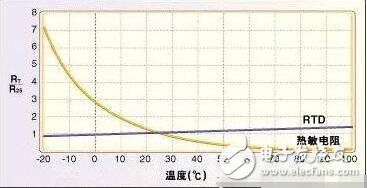
The resistance value of the RTD is a nominal value of 0 °C. 0 °C 100Ω platinum RTD resistance is typically 100.39Ω at 1°C and 119.4Ω at 50°C. Figure 4 is a comparison of the RTD resistance/temperature curve versus the thermistor resistance/temperature curve. The error of the RTD is smaller than that of the thermistor. For platinum, the error is generally 0.01%, and the nickel is generally 0.5%. In addition to the small error and resistance, the interface circuit of the RTD and the thermistor is basically the same.
Thermocouple
The thermocouple is made up of two different metals. It generates a small voltage when heated. The voltage depends on the two metal materials that make up the thermocouple. Iron-constantan (J type), copper-constantan (T type) And chrome-aluminum (K-type) thermocouples are the three most commonly used.
Thermocouples produce very small voltages, usually only a few millivolts. The voltage change of the K-type thermocouple temperature is only about 40μV when the temperature changes by 1 °C, so the measurement system should be able to measure the measurement accuracy of 4μV voltage change to reach 0.1 °C.
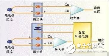
Since the two different types of metals combine to create a potential difference, the connection of the thermocouple to the measurement system also produces a voltage. The connection point is usually placed on the insulating block to reduce this effect, so that the two nodes are at the same temperature, thereby reducing the error. Sometimes the temperature of the insulation block is also measured to compensate for the effects of temperature (Figure 5).
The gain required to measure the thermocouple voltage is typically 100 to 300, and the noise drawn by the thermocouple is amplified by the same factor. A measurement amplifier is typically used to amplify the signal because it removes common mode noise from the thermocouple wires. Thermocouple signal conditioners, such as Analog Devices' AD594/595, are available on the market to simplify hardware interfaces.
Solid state thermal sensor
The simplest semiconductor temperature sensor is a PN junction, such as a PN junction between a diode or a transistor base-emitter. If a constant current flows through the forward biased silicon PN junction, the forward voltage drop will decrease by 1.8 mV for every 1 °C change in temperature. Many ICs use this characteristic of semiconductors to measure temperature, including Maxim's MAX1617, the national half of the LM335, and the LM74. Semiconductor sensors come in a variety of interfaces, from voltage output to serial SPI/microwire interfaces.
There are many types of temperature sensors, and by properly selecting software and hardware, you can find the right sensor for your application.
Temperature sensor application considerations
Selecting a temperature sensor requires more consideration than selecting another type of sensor. First, the structure of the sensor must be chosen such that the temperature of the fluid being measured or the surface being measured is reached within the specified measurement time of the sensitive component. The output of the temperature sensor is simply the temperature of the sensitive component. In fact, it is often difficult to ensure that the temperature indicated by the sensor is the temperature of the object being measured. In most cases, the selection of temperature sensors requires consideration of the following aspects:
(1) Whether the temperature of the object to be tested needs to be recorded, alarmed and automatically controlled, and whether long distance measurement and transmission are required.
(2) The size and accuracy requirements of the temperature measurement range.
(3) Is the temperature measuring component the appropriate size?
(4) When the temperature of the measured object changes with time, the hysteresis of the temperature measuring component can adapt to the temperature measurement requirement.
(5) Whether the environmental condition of the object to be tested is harmful to the temperature measuring element.
(6) If the price is guaranteed, it is convenient to use.
The choice of temperature sensor is mainly based on the measurement range. When the measurement range is expected to be within the total range, a platinum resistance sensor can be used. A narrower range typically requires the sensor to have a fairly high base resistance in order to achieve a sufficiently large resistance change. The large enough resistance change provided by the thermistor makes these sensitive components ideal for narrow measurement ranges. Thermocouples are more suitable if the measurement range is quite large. It is best to include the freezing point in this range because the thermocouple's indexing table is based on this temperature. Sensor linearity within the known range can also be used as an additional condition for selecting a sensor.
Pwm Line Interactive UPS,Simulated Sine Wave,Offline UPS,CPU Control
Shenzhen Unitronic Power System Co., Ltd , https://www.unitronicpower.com