Why is "serial" popular?
From the principle of view, parallel transmission is actually better than serial transmission. In layman's terms, parallel access is like a broad, multi-lane road, while serial transmission is a country road that allows only one car to pass. Take the old and typical standard parallel port (standard parallel port) and serial port (commonly known as COM port) as an example, the bit width of the parallel interface is 8 and the data transmission rate is high; while the serial interface has only 1 bit, the data transmission speed low. The parallel port can transmit one byte during the transmission of 1 bit on the serial port. When the parallel port completes the delivery task of the word "advanced", only the first letter "a" of this word is transmitted in the serial port.
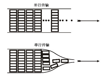
Figure 1: H6A-2-1.TIF parallel interface speed is 8 times faster than serial interface
So why is the current serial transmission method better?
First, parallel transmission technology encounters development difficulties
The bus and interface in the computer are the "big arteries" that transfer data between the host and external devices. As the processor speed continues to rise, the data transmission speed of the bus and the interface also needs to be gradually increased, otherwise it will become a bottleneck for computer development.
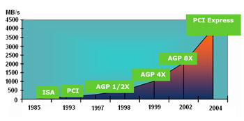
Figure 2 Development of the PC Bus
Let's take a look at the bus. In 1981, the first open-architecture system with the ISA bus as its mark in the first PC used the ISA bus. The data bus was 8 bits and the operating frequency was 8.33MHz. This was considered as "Advanced Technology" at the time. The ISA bus has another name "AT bus." By 286, the bit width of the ISA was increased to 16. In order to maintain compatibility with the 8-bit ISA, the operating frequency was still 8.33 MHz. Although the ISA bus has a data transfer rate of only 16 MBps, it has been the fastest data channel between the motherboard and external devices until the 386 era.
In the 486 era, both PCI and VESA have emerged as two faster bus standards. They have the same bit width (32 bits), but the PCI bus can run asynchronously with the processor. When the frequency of the processor increases, the PCI bus frequency increases. Can still remain unchanged, you can choose three frequencies of 25MHz, 30MHz and 33MHz. The VESA bus and the processor work synchronously. Therefore, as the frequency of the processor is increased, the peripheral device operating frequency of the VESA bus type has to be improved, and the adaptability is poor, so the competitiveness is quickly lost. PCI bus standard became the king of Pentium era PC bus, hard disk controller, sound card to network card, all use PCI slot. The graphics card has a higher requirement for data transmission speed, and a dedicated AGP has emerged.
Parallel data transmission technology has always been an important means to increase the data transmission rate, but further development has encountered obstacles. First of all, because the premise of the parallel transmission method is to use the same timing to propagate signals and receive signals at the same timing, it will be difficult to excessively increase the clock frequency to make the timing of the data transmission and the timing of the clock coincide. The wiring length is slightly different and the data will be different from the clock. The timing of delivery, in addition, increase the clock frequency is also easy to cause interference between the signal lines, resulting in transmission errors. Therefore, it is difficult to achieve high speed in the parallel method. From the point of view of manufacturing costs, increasing the bit width will undoubtedly lead to an increase in the number of wiring on the motherboard and expansion board, and the cost will increase accordingly.
In terms of external interfaces, we know that the speed of the IEEE 1284 parallel port can reach 300kBps. Compression technology can increase to 2MBps when transferring graphics data. The data transfer rate of the RS-232C standard serial port is usually only 20kbps. Data transfer on the parallel port The rate will undoubtedly win. For more than a decade, the parallel port has been the preferred connection method for printers. For a text-only pin printer, the speed of the IEEE 1284 parallel port is more than sufficient. However, the situation has changed for laser printers that have been repeatedly accelerated in recent years. The author used Epson 6200L when printing 2MB images, the speed difference is not obvious, but when printing 7.5MB size image files, from the click "print" to the final output, using the USB interface for 18 seconds, and when using the parallel port It took 33 seconds. This test result shows that the current parallel port has been difficult for a popular laser printer.
Second, USB, serial interface for fire rebirth
The phoenix nirvana revived. In 1995, the USB interface introduced by Compaq, Intel, Microsoft, and NEC first appeared on PCs. Since 1998, it has entered a large-scale practical stage. It is the successor to the IEEE 1284 parallel port and RS-232C serial port. USB has now become very popular.
Although USB has only one bit wide, the data transfer speed is higher than that of the parallel port, and it has a lot of room for development. The adaptability of the communication speed of the USB device makes it possible to automatically select HS (High-Speed, 480 Mbps), FS (Full-Speed, 12 Mbps), and LS (Low-Speed, 1.5 Mbps). One of the patterns. The USB bus also has automatic device detection capabilities. After the device is plugged in, the operating system software automatically detects, installs, and configures the device, eliminating the need to shut down the PC when adding or removing devices.

Figure 3 USB using differential mode signal transmission

Figure 4 Differential transmission mode has better anti-interference performance
The reason why the USB interface can obtain a high data transmission rate is mainly because it abandons the conventional single-end signal transmission method and instead uses a differential signal transmission technology, effectively overcoming the signal transmission line due to the antenna effect. The resulting interference, as well as crosstalk between transmission lines. The two data lines in the USB interface are intertwined to form a twisted pair structure, as shown in Figure 3.
FIG. 4 shows a choke coil formed by winding two signal wires around a ring-shaped ferrite core. In the single-end signal transmission mode, when the line is subjected to electromagnetic radiation to generate a common-mode current, the magnetic field is superimposed to become a higher line impedance. This reduces the interference, but the effective signal is also attenuated. In differential transmission mode, common-mode interference is canceled by the core but no additional line impedance is generated. In other words, the use of common mode choke coils in differential transmission mode can achieve the purpose of anti-interference without affecting signal transmission.
In the differential signal transmission system, the transmission line can achieve good anti-jamming performance without shielding and reduce the connection cost. However, due to the relatively low signal level of the 3.3V USB interface, the maximum communication distance is only 5m. The USB specification also limits the number of physical layers to no more than seven layers, which means that users can use up to five connectors to place a USB device at a maximum distance of 30m from the host.
In order to solve long-distance transmission problems and expand the application scope of USB, some manufacturers added new features to the USB specification, such as Powered USB and Extreme USB. The former increased the power supply capability of USB, and the latter extended the transmission distance of USB. For example, with CAT5 cable and RJ45 connector, it can be easily extended to 100m; using fiber can be extended to 2km, but the cost is higher than CAT5.
Small knowledge: Twisted pair, twisted together, what is good?
The purpose of the twisted pair twisted with each other is to use the electromagnetic field generated by the current in the copper wire to interact to cancel the interference of the adjacent lines and reduce the interference from the outside. The number of times each pair of wires are wound on each inch determines the ability of anti-jamming and the quality of communication. The closer the winding is, the higher the communication quality is, and the higher the supported data transmission rate, the higher the manufacturing cost. Twisted pair can obtain good anti-jamming performance even if there is no shielding layer outside, so the use of CAT5 unshielded twisted pair (UTP) in LAN can meet the requirement of transmitting 100Mbps signal, and the communication distance can reach 100m.
Third, differential signal technology: high-speed signal transmission of the golden key
The history of computer development is the history of pursuing faster speeds. With the increase of bus frequency, all signal transmissions have encountered the same problem: the more electromagnetic interference between the lines, the higher the probability of failure of data transmission, the traditional single-ended Signal transmission technology can not meet the needs of high-speed bus. Therefore, differential signal technology has begun to be applied in various high-speed buses. We already know that the secret of USB to achieve high-speed signal transmission lies in the adoption of differential signal transmission.

Figure 5 Differential Signal Transmission Circuit
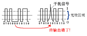
Figure 6 Single-ended signal transmission

Figure 7 Differential Signal Transmission
Differential signal transmission technology is a kind of data transmission and interface technology that appeared in the 1990s. Compared with the traditional single-end transmission method, this technology has the characteristics of low power consumption, low bit error rate, low crosstalk, and low radiation. The transmission medium can be a copper PCB connection or a balanced cable with a maximum transmission rate of 1.923 Gbps. The third-generation I/O technology (3GIO) advocated by Intel, the core technology of the physical layer is the differential signal technology. So, what is the difference between differential signal technology?
We know that in the traditional single-ended communication, one line transmits one bit. High indicates 1 and low indicates 0. If the signal is disturbed in the data transmission process, the high and low level signals may completely generate large disturbances that break through the critical value. Once the high level signal or the low level signal exceeds the critical value, the signal will go wrong, as shown in FIG. 6 .
In the differential transmission circuit, when the output level is a positive voltage, it represents a logic "1", when a negative voltage is output, it represents a logic "0", and the output of a "0" voltage is meaningless, it neither represents a "1" nor Represents "0". In the differential communication shown in FIG. 7 , the interference signal enters two adjacent signal lines at the same time. At the signal receiving end, two identical interference signals respectively enter the two inverting input terminals of the differential amplifier, and the output ends. The voltage is 0. So, differential signal technology has strong immunity to interference signals. For serial transmission, LVDS can be lower than external interference; for parallel transmission, LVDS can not only resist external interference, but also can resist crosstalk between data transmission lines.
For the above reasons, as long as a low voltage differential signal (LVDS) is used in an actual circuit, an amplitude of about 350 mV can satisfy the requirement for close distance transmission. Assume that the load resistance is 100Ω. When using LVDS to transmit data, if the twisted pair length is 10m, the transmission rate can reach 400Mbps. When the cable length is increased to 20m, the rate is reduced to 100Mbps. When the cable length is 100m, The speed can only reach about 10 Mbps.
LVDS was first proposed by National Semiconductor Corporation as a high-speed serial signal transmission level. Because of its advantages such as fast transmission speed, low power consumption, strong anti-jamming capability, long transmission distance, and ease of matching, it quickly gained a lot of chip manufacturers and Applicants are favored by the TIA/EIA (Telecommunication Industry Association/Electronic Industries Association) and become the organization's standard (ANSI/TIA/EIA-644 standard).
In close-range data transmission, LVDS can not only achieve high transmission performance, but also a low-cost solution. LVDS devices can be fabricated in an economical CMOS process, and high speeds can be achieved using low cost Category 3 cables and connectors. At the same time, because LVDS can adopt the lower signal voltage, and the driver adopts the constant current source mode, its power will not change with the frequency almost, thus make it possible to increase the data transmission rate and reduce the power consumption. Therefore, USB, SATA, PCI Express, and HyperTransport commonly use LVDS technology. The LCD control circuit transmits pixel brightness control signals to the LCD screen, and also adopts the LVDS method.
Fourth, the new serial era has arrived
Differential transmission technology not only breaks through the speed bottleneck, but also saves space by using a small connection. Therefore, in recent years, in addition to USB and FireWire, many serial connection standards featuring differential signal transmission have emerged, covering almost the motherboard bus and external I/O ports, presenting a shift from parallelism to the new serial era. The trend is that the application of serial interface technology will enter its heyday in 2005 (Figure 8).

Figure 8 All I/O Technologies Will Use Serial Mode
â— LVDS technology, breaking the chipset transmission bottleneck
With the increase of computer speed, the communication speed between the CPU and the Northbridge chip, between the Northbridge and Southbridge, and various device buses connected to the chipset affects the overall performance of the computer. However, the FR4 printed circuit board that has been used has limited inter-symbol interference due to skin effect and dielectric loss, which limits the transmission rate.
As the speed of traditional parallel synchronous digital signals will reach the limit, designers are turning to finding ways out of high-speed serial signals because serial bus technology can not only achieve higher performance, but also minimize the number of chip pins. Simplify board layout and reduce manufacturing costs. Intel's PCI Express, AMD's HyperTansport, and RAMBUS's third-generation I/O bus standards (3GI/O) all invariably use low-voltage differential signaling (LVDS) as a next-generation high-speed signal level standard.

Figure 9 PCI Express 1X Data Channel
A typical PCI Express channel is shown in Figure 9. Both sides of the communication consist of two differential signal pairs that form a duplex channel, one for transmission and one for reception. Four physical lines form PCI Express 1X. 1X, 2X, 4X, and 16X are defined in the PCI Express standard. PCI Express 16X has the most physical lines (16×4=64).
Even with the lowest-profile 1X architecture, it is possible to transmit data at 2.5 GHz in both directions simultaneously, and the bandwidth reaches 5 Gbps, which also exceeds the bandwidth of the traditional PCI bus 1.056 Gbps (32 bits x 33 MHz). Moreover, the PCI bus is a shared bus implemented via a bridge, while PCI Express uses a so-called "end-to-end connection" (Figure 10). Each device can enjoy its own bus bandwidth and can therefore achieve higher performance than PCI. .

Figure 10 PCI Express End-to-End Connection Eliminates Bridges
AMD's HyperTransport technology is very similar to PCI Express. It also uses LVDS data channels. Its operating frequency ranges from 200MHz to 1GHz, and its bit width can be flexibly selected to 2, 4, 8, 16 or 32 bits depending on the bandwidth requirements. HyperTransport technology is now used for rapid communication between the North and South Bridges, and will be used for other chip connections in the future.
â— Serial ATA, insert wings for high-speed hard disks
Prior to ATA-33, 40 parallel data lines were used. Because of crosstalk between data lines, the signal frequency was limited. So starting with ATA-66, the ATA data line adds a ground wire between the two wires to reduce mutual interference. After the ground wire is added, the distributed capacitance C2 still exists between the data line and the ground line, which still cannot solve the interference problem completely, and the maximum frequency of the parallel ATA interface stays at 133 MHz. In addition to the root cause of signal interference, parallel PATA still has problems such as hot swapping and poor fault tolerance, and the adoption of Serial ATA has not only completed the transformation but also solved the problem.
Serial ATA is Intel's concept introduced on IDF 2000. Since then, Intel has jointly launched several SATA giants such as APT, Dell, IBM, Seagate and Maxtor. At the IDF2002 Spring Forum, the SATA 2.0 specification has also been announced.
Serial ATA interface includes 4 data lines and 3 ground lines, a total of 7 physical connections. The current SATA 1.0 standard has a data transfer rate of 150MBps, slightly faster than the ATA-133 interface at 133MBps, but future SATA 2.0/3.0 can be increased to 300MBps to 600MBps. From the current trend of hard disk speed growth, the SATA standard can at least meet the requirements of the next few years.
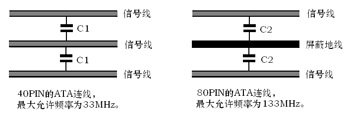
Figure 11 Inter-line crosstalk in Parallel ATA
â— FireWire, image transmission is even more powerful
FireWire was drafted by Apple Computer in 1986 and introduced by the Institute of Electrical and Electronics Engineers (IEEE) in 1995 as IEEE 1394. It is another high-speed serial communication standard beyond USB. The earliest application target of FireWire is to transmit digital image signals for video recording devices. Currently, the application field has spread to DV, DC, DVD, hard disk recorders, TV set-top boxes and home game machines.
The FireWire cable has six cables, two pairs of twisted pairs form two separate channels, and the other two are power and ground. SONY made improvements to FireWire, discarding the power cord and ground wire to form a streamlined FireWire with only two pairs of twisted pairs, and gave it a nice name i.Link.
FireWire data transfer rate is comparable to that of USB. The single-channel bandwidth is 400Mbps and the communication distance is 4.5m. However, the IEEE 1394b standard has expanded the single-channel bandwidth to 800 Mbps. In the new IEEE 1394-2000 standard, the maximum data transmission rate is determined to be 1.6 Gbps. The maximum length of the connecting cable between adjacent devices can be extended to 100 m. .
Fifth, the serial port to red day?
After reading this article, if someone asks you better questions about serial communication and parallel communication, you may be able to blurt out: serial communication is good! However, I would like to tell you that the new serial port has become popular because of the use of four signal lines instead of the traditional two signal line signal transmission methods, and the change from single-ended signal transmission to differential signal transmission. The basic principle of “higher parallel communication speed at the same frequency†is never wrong. Parallel strategies that increase the data transfer rate by increasing the bit width will still play an important role.
Technological advances are endless and endless, and no technology can ever be applied. After the computer technology enters the THz era in the future, the requirement for signal transmission speed will be even higher. Can differential transmission technology still meet the requirements? Do you need another, better technology to complete another breakthrough in frequency? Let us pay attention together.
Pin Header,Smd Pin Header,Double Row Pin Connector,Environmentally Friendly Pin Headers
Shenzhen Jinyicheng Electronci Technology Co.,Ltd. , https://www.jycconnectors.com