Design scheme of driving TFT color screen based on STM32 FSMC interface
TFT-LCD technology is a high-tech combination of microelectronic technology and LCD technology. As people's requirements for image clarity, refresh rate, and fidelity are getting higher and higher, the application range of TFT-LCD is wider and wider. This paper proposes a design scheme that can directly drive the digital LCD screen. The scheme first introduces the working principle of the TFT digital color screen. The hardware circuit and software program designed by the FSMC interface of the STM32 processor can effectively control the display control chip. . The display is clear and fluent in real-world applications, and the CPU has enough time to process the user program. The scheme can be successfully applied to the human-machine interface display of the computerized flat knitting machine, and the hardware circuit structure is simple and the control mode is flexible, and can also provide reference for other types of interface chips.
0 Preface
With the continuous updating of electronic products, the development of various display interfaces is increasing. Due to the high cost performance of TFT color screens, they are widely used as display screens in various electronic devices. At present, there are many schemes for driving TFT color screens, and a terminal type single-chip microcomputer can be driven by a bottom-end single-chip microcomputer. Such a module is relatively expensive, and of course it is very convenient to use.
As long as the MCU sends a few bytes of commands to the TFT through the serial port or parallel port, you can display the effect you want on the screen. This design uses the STM32's FSMC bus to directly drive the TFT digital color screen. This scheme automatically configures the corresponding registers to send data to the TFT digital color screen without CPU involvement, allowing the CPU enough time to process other programs.
1 Introduction to STM32
STM32 is a family of 32-bit microcontrollers based on the ARM core Cortex-M3. The Cortex-M3 core is specifically designed for low power and price sensitive applications with outstanding energy efficiency and processing speed. By adopting the Thumb-2 high-density instruction set, the Cortex-M3 core reduces system memory requirements, while fast interrupt processing meets the high real-time requirements of the control domain, enabling STM32 series microcontrollers based on this core design to be superior. The price/performance ratio is for a wider range of applications.
The STM32 family of microcontrollers offers users a wide range of choices for multi-directional embedded system design in industrial control, smart appliances, building security, medical devices and consumer electronics. The STM32 series adopts a new type of memory expansion technology---FSMC, which has unique advantages in external memory expansion, and can easily expand different types of large-capacity static memories according to the application requirements of the system.
2 TFT color screen module works
This design uses a 3.2-inch LCD screen with a resolution of 320 & TImes; 240, and uses the ILI9341 chip to control the LCD screen.
The control chip circuit of the LCD screen is very complicated. A memory location in GRAM corresponds to a pixel of the display. Inside the chip, there is a circuit that converts the data of the GRAM memory cell into a control signal of the liquid crystal screen, so that each dot presents a specific brightness and color, and these points are combined to become a display interface. The ILI9341 has main configuration pins and control signal lines that can be used to operate the chip in different modes depending on its settings; communicate with the MCU using the 8080 interface or SPI interface; and what mode is used with the 8080 interface. The MUC communicates with the ILI9341 via the SPI or 8080 interface to access its address counter (AC), control register (CR), GRAM, and an LED controller. The LCD itself does not emit light. It needs to be displayed by means of a backlight. The LED controller is used to control the backlight of the LED in the LCD module. LI9341 uses 8080 communication timing operation. The 8080 interface of ILI9341 has 5 control signal lines: write enable signal line WRX, read enable signal line RDX, reset signal line RESX, chip select signal line CSX, distinguish data and command signal line D. /CX. In addition to the control signal, there is a data signal line.
3 overall design hardware design
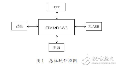
This article connects the RGB interface digital screen with the FSMC interface of the STM32F103VE chip, and uses DMA to read the display data from the off-chip FLASH. DMA is direct memory access. After the CPU only needs to configure the DMA-related registers, the DMA controller will automatically transfer data from one address to another without taking up CPU time. This article uses STM32F103VE chip external connection FLASH for video memory, the overall hardware scheme shown in Figure 1.

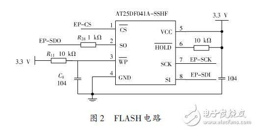
Because the data of the picture is too large, an external FLASH memory is needed to store the picture data. The circuit is shown in Figure 2.

The AT25DF041A chip used in this design is a serial interface flash device. The flexible architecture AT25DF041A erases and eliminates the granularity as small as 4 KB, making it ideal for data storage, eliminating the need for additional data storage E2PROM devices.
4 software design
The software of this design mainly has hardware layer configuration and display driver function. The hardware layer configuration is mainly the input/output of the I/O port of the STM32 and the register configuration related to the FSMC. The display driver function is mainly to send control commands and data to the TFT color screen, in addition to some simple drawing functions.
4.1 Introduction to FSMC
The FSMC is a flexible static storage controller. The STM32 chip can control NOR FLASH, PSRAM and NAND FLASH memory chips using FSMC [3]. Here, only the FSMC's NOR/PSRAM mode is used to control the LCD, so only the NOR FLASH control signal line section needs to be analyzed.
0&TImes;60000000 ~0x6FFFFFFF in the address map of the STM32 addressing space are directly addressable devices such as PSRAM and NOR FLASH. When the external NOR FLASH is connected and the FSMC peripheral is set to work normally, when the data 0xFFFF is written to the 00&TImes;60000000 address, the FSMC will automatically convert the data into the corresponding level signal write data on each signal line.
4.2 Simulating 8080 Timing with FSMC
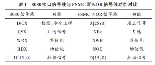
The timing of the FSMC write NOR timing is very similar to that of the 8080 interface. The signal line pairs for them are shown in Table 1.

In order to simulate the 8080 timing, connect A0 in the FSMC address line to D\CX of 8080. When A0 is low, the signal of data line D[15:0] will be interpreted as ILI9341 command. If A0 is high. The transmitted signal is understood as data. Therefore, when transmitting data, it is only necessary to write data to the odd addresses of addresses 0x6xxxxxx1, 0x6xxxxxx3, 0x6xxxxxx5. At this time, the address line A0 (D/CX) will be high; when the command needs to be sent, the even addresses are 0x6xxxxxx0, 0x6xxxxxx2, 0x6xxxxxx4. When writing data, the address line A0 (D/CX) will be low and this data will be interpreted as a command. Using the pointer variable in the code to write data to different address locations, the FSMC can simulate that the 8080 interface writes control commands or GRAM data to the ILI9341.
Reverse Conducting Thyristor(RCT)
Reverse Conducting Thyristor(RCT) is also called Reverse- appreciation Thyristor.The characteristic is that a diode is connected in reverse parallel between the anode and cathode of thyristor, so that the transmitting junction of anode and cathode is short-circuited.As a result of this special circuit structure, it has high voltage resistance, high temperature resistance, short turn-off time, low switching voltage and other good performance.For example, the turn-off time of the reverse thyristor is only a few microseconds, and the working frequency is dozens of KHZ, which is better than the fast thyristor (FSCR).This device is suitable for switching power supply and UPS uninterrupted power supply. One RCT can replace one thyristor and one continuous current diode respectively.
Reverse Conducting Thyristor,Original Reverse Conducting Thyristor,New Reverse Conducting Thyristor,Reverse-Conducting Thyristor 2200V
YANGZHOU POSITIONING TECH CO., LTD. , https://www.cndingweitech.com