Intermediate relay principle and selection requirements that engineers must understand
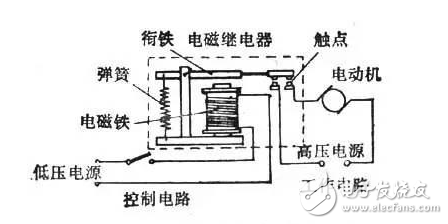
Relays are generally used to control large currents with small currents. It consists of a control loop and a load loop in the automatic control circuit, which is equivalent to an automatic switch. Used for control circuits, protection circuits, and conversion circuits.
The primary function of the relay is for signal detection, transmission, conversion or disposal. The circuit current of the on/off circuit is generally small, and is generally used in the control circuit to control weak signals. The primary function of the contactor is to turn the main circuit on or off. The main circuit refers to whether a circuit works or not is marked by the circuit being turned on. The main circuit concept corresponds to the control circuit. Generally, the main circuit passes a larger current than the control circuit.
Intermediate relay: used in relay protection and automatic control systems to increase the number and capacity of contacts. It is used to pass intermediate signals in the control circuit. The structure and principle of the intermediate relay are basically the same as those of the AC contactor. The main difference with the contactor is that the main contact of the contactor can pass a large current, and the contact of the intermediate relay can only pass a small current. Therefore, it can only be used in control circuits. It generally has no main contacts because the overload capability is relatively small. So it uses all the auxiliary contacts, the number is more. The new national standard defines the intermediate relay as K, and the old national standard is KA. It is usually powered by a DC power supply. A few use AC power.

Relays are mainly divided into general relays and solid state relays. A general relay converts a control signal into a mechanically operated electromagnet and a switch electrical switch. The intermediate relay is one of the most basic relays.
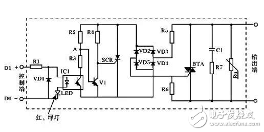
The solid state relay is a contactless relay. It consists of microelectronic circuits, discrete electronic devices, and power electronic power devices. Can be divided into input circuit, electrical isolation part, output circuit composition. As shown in the figure below is a schematic diagram of a typical solid state relay circuit:

Typical solid state relay circuit schematic
Intermediate relay selection needs to consider the elements
1 Geographical climate factors
Mainly refers to the altitude, ambient temperature, humidity, and electromagnetic interference and other factors. Considering the universal applicability of the control system, taking into account the special nature of reliable operation for many years, the key parts of the device must be fully sealed with high insulation and strong electrical resistance (metal cover sealing or plastic sealing type, metal cover sealing products are better than plastic sealing products) ) Intermediate relay products. Because only fully sealed relays have excellent long-term tolerance to harsh environmental performance, good electrical contact stability, reliability and switching load capacity (not affected by external climate).
2 Mechanical action elements mainly refer to stress, impact, impact and other stress factors. For the control system, the anti-seismic stress effect and the anti-mechanical stress acting ability are mainly considered, and a small intermediate relay adopting a balanced armature mechanism should be selected.
3 Excitation coil input parameter elements mainly refer to over-excitation, under-excitation, low-voltage excitation and high-voltage (220 V) output isolation, temperature change effects, long-distance wired excitation, electromagnetic interference excitation and other parametric elements, which are to ensure power system automation devices. Factors that must be carefully considered for reliable operation. Excitation according to the excitation amount specified by the small intermediate relay is a necessary condition to ensure reliable and stable operation.
4, control voltage, must know the actual use of the control voltage, also known as coil voltage. Generally, the relays are given the rated control voltage, but in general, the relay is activated at about 70-80% of the rated voltage. The relay reset does not mean that there is no voltage to reset. In fact, the general situation is less than 15% to ensure reset. So if the control loop has a leakage voltage. Need to consider this impact. The state of action between them is not clear enough.
5, contact structure, intermediate relay common contact structure is single-pole double-throw structure. That is, 1 normally open 1 normally closed to form a group. Such a structure is often referred to as a pole. For example, 2 poles and 4 poles indicate that 2 groups are normally open and normally closed, and 4 groups are normally open and normally closed. In the selection, it is necessary to specify the number of normally open normally closed points that need to be used.
6, voltage and current, also known as contact capacity or load capacity, actually includes voltage and current. But in fact, when choosing, it must be determined separately. To give a clear load voltage, and load current to better confirm the relay that can be selected. Another type of load that needs special attention is the type of load. Here only need to remember under the inductive load. Its junction voltage and current are smaller than under resistive loads. This difference will be stated in the intermediate relay data.
7, the installation method, why is the installation method different? This is because the intermediate relay is generally not directly equipped with a base. When selecting a good relay, you need to confirm the base model. In the industrial control environment, the rail mounting method is actually used. This type of base is also used the most. Also like the pcb board soldering base. The back is connected to the base. In fact, this choice is not to choose the relay but to choose the base.
8, contact output (switching circuit) parameter elements mainly refers to contact load properties, such as lamp load, capacitive load, motor load, inductor, contactor (relay) coil load, resistive load, etc.; contact load Measured value (open circuit voltage value, closed circuit current value), such as low level load, dry circuit load, small current load, high current load, etc.
Any automation equipment must actually determine the actual load characteristics and load value required. It is especially important to choose a suitable relay product. The failure or reliability of the relay is unreliable, mainly referring to whether the contact can complete the function of the specified switching circuit. If the actual load of the switch is inconsistent with the switching load specified by the selected relay, reliability will not be discussed.
Electric Test Pen ,Battery Detector,Circuit Tester,Voltage Test Pen
YINTE TOOLS (NINGBO) CO., LTD , https://www.yinte-tools.com