On how to implement the design of high power factor LED driver
With the application of LED lamps in many fields, such as commercial lighting and home lighting, LED lighting has fully replaced traditional incandescent lamps and fluorescent lamps. Compared with traditional lighting, LED lighting is more expensive than traditional lighting. However, it has significant advantages such as energy saving, high light efficiency, long life and no pollution. Therefore, LED lighting can be recognized by the market in a short time. In addition, with the uncontrolled consumption of energy resources, lighting products with energy-saving performance have been promoted by government organizations. Energy organizations in some countries have also issued relevant policies to subsidize lighting products that meet their standards. For example, if the power factor of commercial lighting products is greater than 0.9, and household use is greater than 0.7, it is one of the mandatory requirements of the US Energy Star. Therefore, while paying attention to the high light efficiency and long life characteristics of LED lamps, it is particularly important to design LED drive solutions with high power factor and high performance under the premise of ensuring low component cost.
1 Overview of the development of LED lighting
Consumers have switched from traditional lighting to LED lighting has been considered a general trend, an article pointed out that LED lighting can save 80% of energy compared to incandescent lamps, and its life can be as long as 10-20 years. In addition, compared to compact energy-saving lamps, LED lamps do not contain substances harmful to the environment, such as mercury, mercury, and other heavy metal substances, and there is no problem of long time to warm up lamps like energy-saving lamps (CFL) at startup, so global resources are tight. Under the environment of China, balanced to the strong relationship between the environment and energy, the policy will also accelerate the promotion of LED lighting, because LED lighting is far superior to traditional lighting products in terms of luminescence principle, energy saving, and environmental protection, although in a short time The cost of LED lighting is very high. For example, the retail price of traditional 60W incandescent lamps is only less than 1/10 of that of 7W LED lamps. Therefore, the affordability of LED lamps for home users at this stage is still limited. In the commercial lighting market under construction, such as hotels and shopping malls, LED lighting is used, and it is rare to see the shadow of traditional lighting.
This article will mainly discuss the driving part of LED lighting, how to reduce the input current harmonics and improve the input power factor. Developed countries have attached great importance to energy issues in the field of lighting. For example, the European energy standard EVP5 and the US Energy Star have clearly stipulated that the power factor PF of residential lighting drivers must be greater than 0.7, and commercial lighting is greater than 0.9.
2 Buck LED driver
2.1 Introduction and description of buck LED driver
The three commonly used basic power conversion structures usually refer to buck buck, boost BOOST and buck-boost BOOK-BOOST structures. They are all non-isolated, and the input and output voltages are connected to the same ground line. Each structure has its own characteristics, such as static voltage conversion rate, input and output current characteristics, output voltage ripple and the most important frequency response characteristics. The most common and simple structure is the buck BUCK structure, usually designed The choice of buck structure is based on the fact that the output voltage on the LED is always less than the input voltage, and a non-isolated structure can be used. Here is another feature of the buck structure, because the current of the main switch tube rises from zero to the rated value in each switching cycle, so its input current is always discontinuous, while the output current is continuous , This is because the output current is provided by the inductor and the output capacitor.
In the actual LED driver design, a buck structure is adopted for medium and high LED voltage output. Because of its simple structure and obvious advantages in component cost and conversion efficiency, it is widely used.

Figure 2.1: Circuit diagram and test value of buck structure
Figure 2.1 is a conventional BUCK step-down circuit. The chip is NXP ’s SSL2109 controller. It can be seen on the schematic that its peripheral components are very few, the circuit is very simple, and the inductor only requires a winding, unlike other controllers. It must rely on another auxiliary winding to power the chip. Here, it uses a high-voltage ceramic capacitor C5, which is connected to the grid of the main switch tube for charging. Therefore, after the chip is started, the normal working level comes from this capacitor. The role. In terms of efficiency, it can reach more than 90%, the disadvantage is that the power factor is only about 0.55, as shown by the curve on the right side of Figure 2.1.
2.2 Working principle of step-down structure LED driver
The main operation waveform of the buck BUCK circuit is shown in Figure 2.2. The purple channel is the current waveform between the drain and source of the main switch Q1, the green channel is the drain voltage waveform of the main switch Q1, and the blue channel is Input current waveform, the yellow channel is the input voltage waveform.
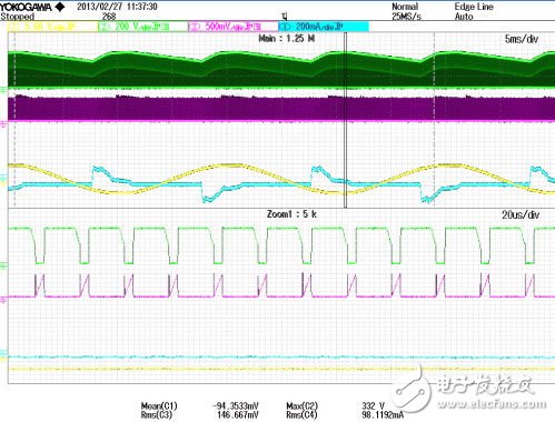
Figure 2.2: Test waveform of buck structure
It can be seen that the average value of the current flowing through the main switch tube is basically a horizontal line, the main reason is that the rectified filter capacitor (C1, C2) has a large capacity, and the storage voltage after its full is sufficient to discharge the entire cycle, Therefore, the input voltage will always be higher than the output voltage. The current flowing through the switch in each cycle is converted into a voltage signal through the resistor R5 and compared with the detection of the chip pin 4. The level of the current reference pin in the chip is generally a fixed value. Usually about 0.5V, when the reference value is reached, the main switch will stop working, and then wait for the next turn-on signal, that is, when the lowest valley voltage on the switch is detected, the chip will provide the turn-on drive signal to the gate of the main switch . Therefore, the current of the switch tube is basically the same every cycle, which causes the change of the current on the input line (light blue channel in Figure 2.2) does not follow the change of the input voltage (yellow channel in Figure 2.2), Therefore, in this design, the input power factor will be very low, and the current harmonics are also very large.
ZTTEK Batteries, For 5G backup base station .Customize the lithium ion battery packs according to the application and product requirements of the customers.
Lithium ion battery integration requires a special set of skill and expertise to optimize the performance and battery life.ZTTEK Batteries , using the most advanced technology delivers the best quality battery packs.
Our batteries are safe to use, better performance, higher shelf life and a very low maintenance cost.
48V200Ah Lithium Ion Battery,Lifepo4 Battery 48V 200Ah,Rechargeable Battery 48V 200Ah,48V 200Ah Lifepo4 Battery Pack
Jiangsu Zhitai New Energy Technology Co.,Ltd , https://www.ztbatteries.com