Automotive Network: Application Automation Design and Synthesis Tools
Since its inception in 2003, the AUTOSAR (Automotive Open Systems Architecture) Alliance has been working to change the way in-vehicle networks and electronic control units (ECUs) are designed. AUTOSAR proposes an industry-standard in-vehicle network design methodology that enables the industry to integrate, exchange and transmit functions, data and information within the automotive network. This standard greatly facilitates collaboration between automotive original equipment manufacturers (OEMs) and their Tier 1 suppliers, enabling them to exchange design information in a consistent, clear and machine-readable format.
This article refers to the address: http://
Different parts of a car have different requirements for safety and performance, and the in-vehicle network that supports them must have predictable safety. As automotive technology continues to evolve, a range of bus technologies are available to connect up to 100 different ECUs in luxury cars. These bus technologies typically include LIN, CAN, FlexRay, MOST, and Ethernet-based architectures. If it is impossible to manually manage thousands of information and interactions between these ECUs, automotive designers must use automated design and synthesis tools to predict network performance and adjust vehicle functionality.
Car data bus
A typical modern car will be equipped with various buses and protocols and select the right network from LIN, CAN, FlexRay, MOST and Ethernet. Multimedia/audio-visual signals and automotive surround camera systems require higher data rates, so car manufacturers and OEMs choose to replace MOST with Ethernet on network solutions. But for many standard automotive functions, the bandwidth provided by LIN and CAN And performance is enough.
In the automotive architecture, the ECUs are grouped together to form a "cluster" that is connected by a communication "gateway." Clusters usually share the same type of bus, so to achieve high reliability, high rate standards, FlexRay network is required, but the door lock ECU that requires less high can be responsible for CAN or LIN. ECU gateways often have to connect different types of signals and perform mapping and conversion functions between different bus architectures. The automotive industry places strong demands on increasing safety and compliance with standards such as ISO26262, which in turn improves the performance of in-vehicle networks while reducing manufacturing and component costs. Evolving network standards can adapt to ever-increasing data rates, and automotive cables have reached a safe and low-cost goal. The characteristics and applications of typical automotive network solutions are shown in Table 1.

Table 1: Automotive network bus.
Network timing analysis
Let's take a closer look at the timing analysis of CAN and FlexRay networks. It is useful to understand the basic characteristics and differences of these two types of networks.
CAN network:
CAN is a widely used class of in-vehicle networks operating on ISO 15765-2. The CAN bus provides a high level of system flexibility, making it relatively easy to add new ECU receiver nodes to existing CAN networks without making major hardware or software changes to existing ECU nodes. For automotive designers, this can greatly help them expand or upgrade existing networks or design new variants.
In the real-time operation of the CAN network, the urgency of different types of information exchanged through the network varies greatly. For example, for an ECU that manages engine fuel injection, engine instantaneous load feedback must be obtained immediately, as compared to parameters such as engine temperature that are not required to be known so frequently.
The priority of the information to be transmitted is determined by the "identifier" contained in each piece of information. The priority of the transmission is determined when designing the system and cannot be changed at will. In the CAN architecture, the issue of bus access contention can be resolved by bitwise arbitration of the identifier. The CAN bus does not have a master, so all ECU nodes connected to the bus need to be arbitrated for network usage. If the first bit is "0", this information takes precedence over other information. This is called "dominant" information, and if the first bit is "1", the priority is lowered ("recessive" information). Therefore, the highest priority information can always be transmitted to the intended destination address, but the lower priority information may temporarily exit the bus transmission until the bus is idle. The ECU node that wants to send lower priority information will only retry the transmission when the bus is idle. The information between the ECUs that can be transmitted by the CAN bus can be up to 8 bytes, and the signals transmitted through the CAN are packed into information "frames".
FlexRay network:
The FlexRay protocol is more deterministic than CAN. FlexRay is a "time-triggered" protocol that offers different options for information to be sent to the target address in a precise time frame - accurate to 1μs. FlexRay information can be up to 254 bytes, so it needs to be in the ECU The amount of complex information exchanged between them is large. Compared to CAN, FlexRay has a higher data transfer rate. Since the timing is predetermined, the information needs to be planned in advance and is generally pre-configured or designed by the automotive OEM or Tier 1 supplier partner. In a network using the CAN protocol, the ECU node only needs to know the correct baud rate when communicating, but the ECU node on the FlexRay network must know how the various parts of the network are configured and connected when communicating. Checking and verifying the timing of the FlexRay network is time consuming – so automated timing analysis and packetization of information into time frames can reduce errors and design cycle times.
Define network timing
The first step in simulating the timing of a car network is to accurately define the connections between the ECUs. The software approach proposed by AUTOSAR defines all automotive functions as a collection of software components and maps them to physical ECU hardware. An ECU may have several functions, and internal signals are passed between them. Once the connection is defined, the timing parameters (if known) for each object in the design can be defined. Timing information has multiple external sources; the widely used automotive standard is FIBEX, an XML-based standardized file format defined by the Automation and Measurement Systems Standards Association (ASAM).
The physical path of the example system is shown in Figure 1 and Figure 2. The brake position monitor module is connected to the controller ECU and in turn to the actuator. Within each module, individual software components also have an impact on latency. We will look at the impact of these components on overall system latency.
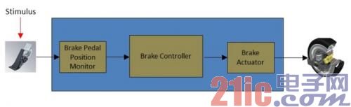
Figure 1: Overview of the brake system signal path.
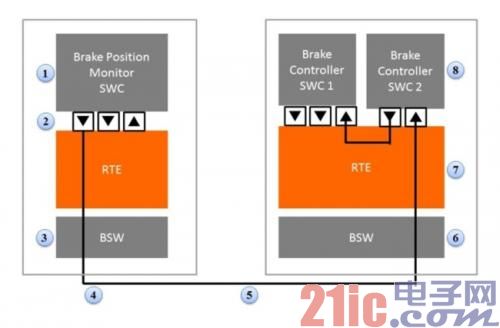
Figure 2: Brake system with AUTOSAR components - detailed timing parameters can be defined.
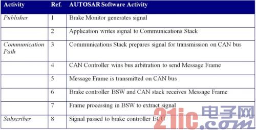
Table 2: Transmission steps for the AUTOSAR brake example.
In the example provided in Table 2, the end-to-end signal path can be up to 100ms. From the actual measurement results, we know that the sender needs 5ms, and the receiver takes 10ms, so the communication path delay can be up to 85ms.
If you use the advanced AUTOSAR component editor, such as Mentor's VSA COM Designer tool, you can enter timing information for each component in the path, but this is also a daunting task. Another method is to import timing and connection information from an external database.
When simulating the CAN bus data path, it is necessary to take into account the uncertainty at the start of the transmission. It may happen that higher priority information occupies the data bus, causing transmission delays. So find the jitter factor that causes the delay variation - usually know ahead of time how many higher priority signals may be on the bus so that the jitter factor can be predicted as accurately as possible. With these parameters and automated design rule checking (DRC), the maximum delay from step (3) to step (7) is 74.5 milliseconds, and such design checks can be passed. This is the "worst case" test, and designers have to believe that path latency will never be worse than this, and it will actually be much better.
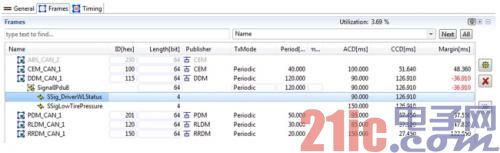
Figure 3: Typical timing report from the VSA COM Timing Analysis Tool showing DRC violations.
Figure 3 shows a typical timing report in which signal path violations are highlighted in red. The overall bus utilization is shown at the top of the table (3.69%).
It also simulates signal timing path prediction through the car gateway. If the signal is sent automatically through the gateway, the shortest available path is required, and the timing path analysis algorithm requires information about all ECU senders and receivers in the signal path. Some gateways may be for diagnostic purposes only, and signals passing through these gateways may have lower priority.
Automotive communication matrix synthesis
The overall definition of automotive network scheduling is typically stored in a "communication matrix" that is part of the central gateway ECU. The design tool solution developed by Mentor can be used to automatically synthesize this database and package all the different information into frames in the correct order.
The AUTOSAR signal information is combined into Protocol Data Units (PDUs) which are then combined into a transmission frame. For CAN and LIN frames, there is one PDU per frame, but one FlexRay frame may contain multiple signal PDUs.
In the FlexRay architecture, timing is deterministic, and the main uncertainty facing designers is frame packing and transmission order. Automotive OEMs and designers invest a lot of time in testing all possible situations in a car to determine worst-case behavior and ensure a greater safety margin for information transmission. This means that in order to ensure a high level of timing safety, the full capacity of the data bus cannot be taken up. The synthesis tool optimizes frame utilization by finding signals with similar paths and timing requirements for packing and scheduling in similar frame time gaps. When using Mentor's timing synthesis tool, the design inputs will include signal and PDU definitions, frame priority, and specific OEM design decisions regarding possible signal paths. Take these into account when generating a complete timing system.
There is a problem in installing a fully defined communication system, that is, it is difficult to have architectural changes in the future, and may require a complete redesign of the network, but the advantages of high speed and certainty of transmission make this method to FlexRay. The application creates great appeal and ensures the car's very high safety requirements. Re-establishing a more advanced communication system with this synthesis tool can shorten the repair cycle.
to sum up
AUTOSAR provides pre-defined standard methods for in-vehicle networking and ECU design. But designers still face challenges in how to improve the efficiency and performance of their designs. By using design automation aids to calculate timing and generate in-vehicle communication systems, you can greatly increase the utilization of valuable network bandwidth while maintaining a safe range of automotive performance. As the complexity of CAN, FlexRay, and Ethernet fusion increases, the use of automated design rule checking and timing performance synthesis tools will help reduce design time and avoid cumbersome manual verification processes.
Since its inception in 2003, the AUTOSAR (Automotive Open Systems Architecture) Alliance has been working to change the way in-vehicle networks and electronic control units (ECUs) are designed. AUTOSAR proposes an industry-standard in-vehicle network design methodology that enables the industry to integrate, exchange and transmit functions, data and information within the automotive network. This standard greatly facilitates collaboration between automotive original equipment manufacturers (OEMs) and their Tier 1 suppliers, enabling them to exchange design information in a consistent, clear and machine-readable format.
Different parts of a car have different requirements for safety and performance, and the in-vehicle network that supports them must have predictable safety. As automotive technology continues to evolve, a range of bus technologies are available to connect up to 100 different ECUs in luxury cars. These bus technologies typically include LIN, CAN, FlexRay, MOST, and Ethernet-based architectures. If it is impossible to manually manage thousands of information and interactions between these ECUs, automotive designers must use automated design and synthesis tools to predict network performance and adjust vehicle functionality.
Car data bus
A typical modern car will be equipped with various buses and protocols and select the right network from LIN, CAN, FlexRay, MOST and Ethernet. Multimedia/audio-visual signals and automotive surround camera systems require higher data rates, so car manufacturers and OEMs choose to replace MOST with Ethernet on network solutions. But for many standard automotive functions, the bandwidth provided by LIN and CAN And performance is enough.
In the automotive architecture, the ECUs are grouped together to form a "cluster" that is connected by a communication "gateway." Clusters usually share the same type of bus, so to achieve high reliability, high rate standards, FlexRay network is required, but the door lock ECU that requires less high can be responsible for CAN or LIN. ECU gateways often have to connect different types of signals and perform mapping and conversion functions between different bus architectures. The automotive industry places strong demands on increasing safety and compliance with standards such as ISO26262, which in turn improves the performance of in-vehicle networks while reducing manufacturing and component costs. Evolving network standards can adapt to ever-increasing data rates, and automotive cables have reached a safe and low-cost goal. The characteristics and applications of typical automotive network solutions are shown in Table 1.
Table 1: Automotive network bus.
Network timing analysis
Let's take a closer look at the timing analysis of CAN and FlexRay networks. It is useful to understand the basic characteristics and differences of these two types of networks.
CAN network:
CAN is a widely used class of in-vehicle networks operating on ISO 15765-2. The CAN bus provides a high level of system flexibility, making it relatively easy to add new ECU receiver nodes to existing CAN networks without making major hardware or software changes to existing ECU nodes. For automotive designers, this can greatly help them expand or upgrade existing networks or design new variants.
In the real-time operation of the CAN network, the urgency of different types of information exchanged through the network varies greatly. For example, for an ECU that manages engine fuel injection, engine instantaneous load feedback must be obtained immediately, as compared to parameters such as engine temperature that are not required to be known so frequently.
The priority of the information to be transmitted is determined by the "identifier" contained in each piece of information. The priority of the transmission is determined when designing the system and cannot be changed at will. In the CAN architecture, the issue of bus access contention can be resolved by bitwise arbitration of the identifier. The CAN bus does not have a master, so all ECU nodes connected to the bus need to be arbitrated for network usage. If the first bit is "0", this information takes precedence over other information. This is called "dominant" information, and if the first bit is "1", the priority is lowered ("recessive" information). Therefore, the highest priority information can always be transmitted to the intended destination address, but the lower priority information may temporarily exit the bus transmission until the bus is idle. The ECU node that wants to send lower priority information will only retry the transmission when the bus is idle. The information between the ECUs that can be transmitted by the CAN bus can be up to 8 bytes, and the signals transmitted through the CAN are packed into information "frames".
FlexRay network:
The FlexRay protocol is more deterministic than CAN. FlexRay is a "time-triggered" protocol that offers different options for information to be sent to the target address in a precise time frame - accurate to 1μs. FlexRay information can be up to 254 bytes, so it needs to be in the ECU The amount of complex information exchanged between them is large. Compared to CAN, FlexRay has a higher data transfer rate. Since the timing is predetermined, the information needs to be planned in advance and is generally pre-configured or designed by the automotive OEM or Tier 1 supplier partner. In a network using the CAN protocol, the ECU node only needs to know the correct baud rate when communicating, but the ECU node on the FlexRay network must know how the various parts of the network are configured and connected when communicating. Checking and verifying the timing of the FlexRay network is time consuming – so automated timing analysis and packetization of information into time frames can reduce errors and design cycle times.
Define network timing
The first step in simulating the timing of a car network is to accurately define the connections between the ECUs. The software approach proposed by AUTOSAR defines all automotive functions as a collection of software components and maps them to physical ECU hardware. An ECU may have several functions, and internal signals are passed between them. Once the connection is defined, the timing parameters (if known) for each object in the design can be defined. Timing information has multiple external sources; the widely used automotive standard is FIBEX, an XML-based standardized file format defined by the Automation and Measurement Systems Standards Association (ASAM).
The physical path of the example system is shown in Figure 1 and Figure 2. The brake position monitor module is connected to the controller ECU and in turn to the actuator. Within each module, individual software components also have an impact on latency. We will look at the impact of these components on overall system latency.
Figure 1: Overview of the brake system signal path.
Figure 2: Brake system with AUTOSAR components - detailed timing parameters can be defined.
Table 2: Transmission steps for the AUTOSAR brake example.
In the example provided in Table 2, the end-to-end signal path can be up to 100ms. From the actual measurement results, we know that the sender needs 5ms, and the receiver takes 10ms, so the communication path delay can be up to 85ms.
If you use the advanced AUTOSAR component editor, such as Mentor's VSA COM Designer tool, you can enter timing information for each component in the path, but this is also a daunting task. Another method is to import timing and connection information from an external database.
When simulating the CAN bus data path, it is necessary to take into account the uncertainty at the start of the transmission. It may happen that higher priority information occupies the data bus, causing transmission delays. So find the jitter factor that causes the delay variation - usually know ahead of time how many higher priority signals may be on the bus so that the jitter factor can be predicted as accurately as possible. With these parameters and automated design rule checking (DRC), the maximum delay from step (3) to step (7) is 74.5 milliseconds, and such design checks can be passed. This is the "worst case" test, and designers have to believe that path latency will never be worse than this, and it will actually be much better.
Figure 3: Typical timing report from the VSA COM Timing Analysis Tool showing DRC violations.
Figure 3 shows a typical timing report in which signal path violations are highlighted in red. The overall bus utilization is shown at the top of the table (3.69%).
It also simulates signal timing path prediction through the car gateway. If the signal is sent automatically through the gateway, the shortest available path is required, and the timing path analysis algorithm requires information about all ECU senders and receivers in the signal path. Some gateways may be for diagnostic purposes only, and signals passing through these gateways may have lower priority.
Automotive communication matrix synthesis
The overall definition of automotive network scheduling is typically stored in a "communication matrix" that is part of the central gateway ECU. The design tool solution developed by Mentor can be used to automatically synthesize this database and package all the different information into frames in the correct order.
The AUTOSAR signal information is combined into Protocol Data Units (PDUs) which are then combined into a transmission frame. For CAN and LIN frames, there is one PDU per frame, but one FlexRay frame may contain multiple signal PDUs.
In the FlexRay architecture, timing is deterministic, and the main uncertainty facing designers is frame packing and transmission order. Automotive OEMs and designers invest a lot of time in testing all possible situations in a car to determine worst-case behavior and ensure a greater safety margin for information transmission. This means that in order to ensure a high level of timing safety, the full capacity of the data bus cannot be taken up. The synthesis tool optimizes frame utilization by finding signals with similar paths and timing requirements for packing and scheduling in similar frame time gaps. When using Mentor's timing synthesis tool, the design inputs will include signal and PDU definitions, frame priority, and specific OEM design decisions regarding possible signal paths. Take these into account when generating a complete timing system.
There is a problem in installing a fully defined communication system, that is, it is difficult to have architectural changes in the future, and may require a complete redesign of the network, but the advantages of high speed and certainty of transmission make this method to FlexRay. The application creates great appeal and ensures the car's very high safety requirements. Re-establishing a more advanced communication system with this synthesis tool can shorten the repair cycle.
to sum up
AUTOSAR provides pre-defined standard methods for in-vehicle networking and ECU design. But designers still face challenges in how to improve the efficiency and performance of their designs. By using design automation aids to calculate timing and generate in-vehicle communication systems, you can greatly increase the utilization of valuable network bandwidth while maintaining a safe range of automotive performance. As the complexity of CAN, FlexRay, and Ethernet fusion increases, the use of automated design rule checking and timing performance synthesis tools will help reduce design time and avoid cumbersome manual verification processes.
Basic Features
1. The terminal has universal mounting feet so that it can be installed on U-rail NC 35 and G-rail NC32.
2. The closed screw guide hole ensures ideal screwdriver operation.
3. Equipped with uniform accessories for terminals of multiple cross-section grades, such as end plates, grouping partitions, etc.
4. Potential distribution can be achieved by inserting a fixed bridge in the center of the terminal or an edge-plug bridge inserted into the wire cavity.
5. The grounding terminal and the N-line slider breaking terminal with the same shape as the common terminal.
6. Using the identification system ZT, unified terminal identification can be realized.
7. The rich graphics enhance the three-dimensional sense of the wiring system.
Din Rail Terminal Block,Din Rail Fuse Terminal Block,Din Rail Busbar Terminal Block,Din Rail Power Terminal Blocks
Sichuan Xinlian electronic science and technology Company , https://www.sztmlchs.com