Gravity remote control car based on Anxin No.1
I. Project design background and overview
With the continuous development of technology, wireless applications are becoming more and more widespread, and remote control toys and model aircraft are becoming more and more popular. The remote control for aircraft models is analog remote control, with flexible azimuth, speed and angle control, while general toys The remote control is a switch quantity, unlike the analog remote control, AD can be used to obtain a variety of states, while the remote control of the switch quantity has only two states of on and off. The general toy remote control, such as the remote control of the remote control car, controls its forward, backward and cornering actions by pressing the button, but this is too boring with the development of the society, and there is no mobile racing game.
The mobile racing game is based on the gravity sensing function of the mobile phone. Since it can be sensed by gravity, why can't we make a separate gravity sensing remote control? This design implements the design of this remote control through a mercury switch. Mercury switches have been used in gravity sensing applications, and there are fewer applications for remote-controlled vehicles. I will design a more complete gravity remote control car.
Second, the project design principle
1, an overview of the principle
This design is divided into two parts, the remote control part and the trolley part. The remote control AD ​​can control the speed of the car, and the tilt remote control can control the movement direction of the car. The remote real-time data will be displayed on the LCD 1602.
2, the hardware design principle
Remote control backplane: plugs in the LCD1604 and can pull out the control pin. It is plugged into the SLH core board through the DuPont line, and the bottom plate is also equipped with a 3-way mercury switch.
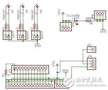
Figure 1 Remote control board schematic
5V to 3.3V control: Because the voltage range of NRF24L01 is about 2.7V~3.6V, and the power supply voltage of Anxin No.1 is greater than 3.6V, it must be connected through the switching circuit. as shown in picture 2.
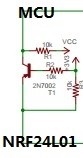
Figure 2 5V-3.3V transfer
Motor drive: As shown in Figure 3, when DIR=1, T3, T4 are on, T1, T2 are off. When PWM is low, T5, T6 are on, T7, T8 are off, motor is forward; when DIR= 0, T1, T2 are on, T3, T4 are off. When PWM is high, T7, T8 are on, T5, T6 are off, and the motor is reversed.
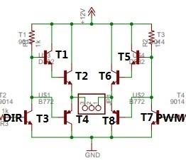
Figure 3 H bridge
3, software design principles
Remote control part: Through the AD conversion of Anxin No.1, an 8-digit precision value is obtained as the speed value of the trolley, and the speed of the trolley can be adjusted by adjusting the potentiometer. There are also 3 mercury switches. The mercury switch can be opened or closed by swinging the remote control to different orientations. The lateral direction of the remote control can be known by detecting the level of the connected pins. The measured speed value and direction are sent to the serial port assistant through the LCD display or through the serial port. Finally, Anxin No. 1 sends the speed value and direction to the car through the wireless module.
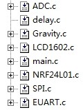
Figure 4 program module of the remote control part
Car part: The wireless module receives the speed value sent by the remote control and stores it in the Anxin No.1. The Anxin No. 1 matching speed value controls the two PWM outputs to control the car speed, and then matches the direction value to control the operation of the gear motor.
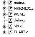
Figure 5 program module of the car part
Floor Standing Display,Signage Advertising Display,Advertising Lcd Screen,Standing Digital Signage
ALLIN , https://www.apiodisplays.com