Analyze the performance advantages of high-speed piezoelectric ceramic drive power
As we all know, the driving power technology of piezoelectric ceramics has become one of the most important application technologies. In addition to its small size, high resolution, fast response, and large thrust, it is widely used in piezoelectric ceramic actuators. In micro-displacement output devices, force generating devices, robots, impact motors, optical scanning and other important fields. At present, the common piezoelectric ceramic devices in China are mainly based on static characteristics. Therefore, the dynamic characteristics of such piezoelectric ceramic driving power sources are not ideal, and the AC load capacity is poor, which is not suitable for use in the dynamic field. For example, piezoelectric ceramic tube impact motor is based on the impact principle, using a sawtooth wave to drive the piezoelectric ceramic tube, so that the piezoelectric motor produces positive and negative rotation, wide frequency response range and high rise and fall rates are such piezoelectric Important dynamic characteristics that must be met by ceramic drive power supplies. However, there are not many researches on this kind of driving power supply in China, and the price is expensive. Therefore, it is necessary to design a piezoelectric ceramic driving power source that meets the above requirements and is inexpensive.
1. Principle and circuit design of high voltage drive power supply
The high-voltage driving power source is mainly composed of a high-voltage direct current power source, a constant current source and a power amplifying circuit. The power amplifying circuit section amplifies the sawtooth wave signal to drive the piezoelectric ceramic tube. In order to obtain a rapid voltage drop rate and cause the piezoelectric ceramic tube to form an impact, a constant current source is needed to help the capacitively loaded piezoelectric ceramic to quickly discharge the charge.
(1) High voltage DC power supply
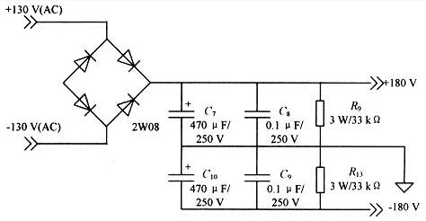
The high-voltage DC power supply part is shown in Figure 1. The power frequency 220V AC power is outputted by the transformer with two 130V AC. After rectification and capacitance filtering by the rectifier bridge, 180V DC power is obtained as the working voltage of the drive circuit.

Figure 1 High voltage DC power supply
(2) Constant current source circuit
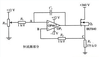
The constant current source circuit is shown in Figure 2. The op amp of this design circuit selects OP467, its rising rate can reach 170V/μs, and has an extremely wide response frequency, which can fully meet the requirements. When the input voltage of point A is VA, according to the principle of virtual short, VA=VB, the input current of the same input and reverse input of the amplifier is 0, then VB=VC, so the current flowing through the FET is constant. I=VA/R3, at this time VGS≥3.5V, the FET is turned on. If the input voltage VA has voltage fluctuation + ΔV, the differential mode gain of the amplifier is close to infinity, so VG increases, VGS increases, the current flowing through the FET increases, VC increases; and because VB=VC, VB It also increases, and finally equals VA, ensuring that the constant current source works normally, and vice versa when ΔV is negative. The current of the constant current source circuit is I=50mA, that is, the voltage VA=7.5V. The purpose of the constant current source circuit is mainly to help the capacitive load piezoelectric ceramic discharge charge, so that the sawtooth wave for driving the piezoelectric ceramic tube has a fast The falling rate, when connected to the power amplifying circuit, connects the drain of the constant current source FET to the point D of the power amplifying circuit of FIG.

Figure 2 constant current source circuit diagram
PowerStack Industrial And Commerical Liquid Cooling ESS
Jiangxi Huayang New Energy Co.,Ltd , https://www.huayangenergy.com