Application of HVDC and UPS in communication
Abstract: By comparing the traditional UPS (UninterrupTIble Power Supply) power supply mode with HVDC (high-voltage direct current, high voltage DC) mode, it is pointed out that the use of HVDC power supply can effectively improve the power supply quality of the equipment room The advantages of investment, high reliability, and low operating cost have gradually become a new power supply mode for operators' computer rooms.
With the safe operation of the UPS power supply system in the communication room, more and more attention has been paid to the industry, and it is also an important link that maintenance personnel are most worried about. The data room in the communication industry generally uses the UPS power system for power supply. Some communication operators have begun to explore and analyze the feasibility of adopting HVDC power supply for communication equipment, and have achieved initial results. The HVDC power supply system has gradually become a new power supply mode for the telecommunications operator's computer room with advantages such as low investment, high reliability, and low operating cost. This article makes some discussion and analysis on the use of HVDC power supply system in the telecommunications operator's computer room.
1 Defects in UPS power supply system and -48 Vdc system
1. 1 UPS power supply structure inverter has low reliability
The UPS power supply system is shown in Figure 1, and its reliability model is shown in Figure 2.
As we all know, DC / AC is the highest cost and lowest reliability link in UPS. According to the current equipment reliability level, the battery reliability Rb = 0.99, while the UPS DC / AC reliability Ri = 0.90, the static switch STS reliability Rs = 0.99, according to Figure 2 can be calculated Power supply reliability of UPS backup energy:
R = RbRiRs = 0. 99 & TImes; 0. 90 & TImes; 0. 99 = 0. 88
It can be seen that the reliability of UPS backup energy in the system is much lower than the reliability of batteries.
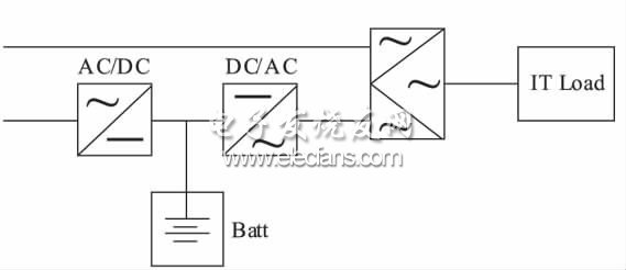
Figure 1 UPS power supply system diagram
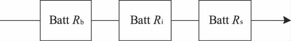
Figure 2 UPS backup energy reliability model
1. 2 The overall utilization rate of the UPS system is low
Each input power distribution of the UPS redundant system may be the main use, and any one of the UPS must be able to carry the full load. Duplex redundant UPS system load rate <35%. The three-phase unbalanced output of the UPS directly leads to the derating of the UPS and has the disadvantage of low stand-alone utilization.
Except for the main road, the input power distribution of the UPS is in no-load standby mode, the use efficiency is very low, the investment in the early construction of the computer room is large and the load planning is wasteful, and it is difficult to expand the system later.
UPS brings an increase in harmonic components of the power supply system, resulting in a decrease in transformer utilization and a weakening of the diesel generator's support capacity, which affects the safety and utilization of the entire power supply system.
It is impossible to eliminate the problem of circulating current between parallel UPS, and it also increases the reactive power loss of the UPS and reduces the reliability of the system.
1. 3 UPS emergency protection and poor maintainability
UPS online maintenance is complicated, online expansion is difficult, and cutover is difficult. Different equipment models and different systems cannot be mutually redundant, and it is difficult to replace key components such as inverters and filter capacitors.
If the UPS inverter fails, the system will switch to bypass power supply, but for certain communication loads, low-quality mains power may cause serious failure risks to the safe operation of the equipment, and the backup battery pack is isolated Protective effects.
1. 4 -48 Vdc system can not meet the requirements of large power consumption communication equipment room
In recent years, due to the rapid development of data communication, the power consumption of the equipment room is increasing. At present, the power consumption of a single rack is increasing rapidly. The measured power consumption of a single rack in a communication room is 9 to 12 kW / rack, and some single racks are up to about 31kW. ! If you still use-48 Vdc, due to the low power supply voltage, 240 Vdc with the high voltage (China Communication Standardization Association "Technical Requirements for 240 V DC Power Supply System for Communication" determines 240 V as the nominal voltage value of the high-voltage DC power supply system in the communications industry) In comparison, according to P = IU, the same power, its current is 240/48 = 5 times of 240 Vdc.
For the same power level, when the voltage is low, the current increases. For cable loss P = I2R, the same cable (the same cable resistance), the line loss is proportional to the square of the current. In order to achieve the same loss level, the cable diameter needs to be increased significantly. For example, 100 kW power consumption, when using 48 Vdc, the current I1 = 100 kW / 48 = 2 083 A, when using 240 Vdc, the current is:
I2 = 100 kW / 240 = 416. 6 A
Thick cables increase costs; high current means greater heat generation, and greater heat generation means more air conditioners are needed for cooling.
2 Feasibility analysis of HVDC replacing UPS
2. 1 HVDC replaces the advantages of traditional UPS
The schematic diagram of traditional UPS power supply is shown in Figure 3. The schematic diagram of HVDC power supply is shown in Figure 4. There is one less DC / AC inverter and AC / DC rectifier inside the server rack than the traditional UPS, which greatly improves the efficiency of the power supply system and reduces the heat loss of the power supply system. The reduction in heat loss also reduces the configuration of the air conditioner. The application of the HVDC power supply method can save 10% to 20% of electric energy than the UPS power supply.
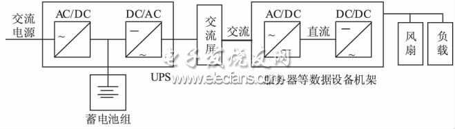
Figure 3 Schematic diagram of traditional UPS power supply
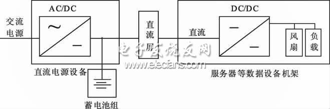
Figure 4 HVDC power supply schematic
Customizable Adapters,Custom Power Adapters,Customizable Usb Adapters,Thunderbolt Otg Adapter Cable
Dongguan Pinji Electronic Technology Limited , https://www.iqdatacable.com